Light input/output terminal module of the optical components and beam converting apparatus

a technology of light input/output terminal and optical components, which is applied in the direction of optical fibers with multi-layer cores/claddings, instruments, light guides, etc., can solve the problems of preventing damage to jackets or the like of sleeves, unable to effectively release light in the cladding of optical fibers, and unable to effectively transfer light. , to achieve the effect of effectively transferring the leaked light, preventing damage, and improving the rate of removing the leaked ligh

Active Publication Date: 2009-04-09
FURUKAWA ELECTRIC CO LTD
View PDF5 Cites 22 Cited by
  • Summary
  • Abstract
  • Description
  • Claims
  • Application Information

AI Technical Summary

Benefits of technology

[0062]According to the present invention, since the jacket tube is integrally fusion-bonded to the cladding, it is possible to provide the light input/output terminal module of the optical component enabling to improve the rate of removing the leaked light in the cladding to prevent the damage. Since the light input/output terminal module of the optical component of the invention includes the jacket tube and the flange, it is possible to effectively transfer the leaked light from the cladding to the jacket tube, and then to dissipate outside through the flange.
[0063]Furthermore, since the coreless fiber having the identical refractive index to that of the core of the optical fiber is connected by fusion splicing to the end face of the optical fiber, the diameter of the beam is enlarged at the end face of the optical fiber to lower the optical power density so that the optical fiber, optical component, optical devices or the like can be prevented from being damaged. In addition, according to the present invention, even if the fiber patch cord has a large optical broadening angle in the coreless fiber, and even if the incident light in the optical fiber has a large optical power densit

Problems solved by technology

However, there are following problems in the above described conventional optical input/output terminal module.
There is a problem in which the light transmitting in the cladding of the optical fiber is not effectively released, since the refractive index of the inorganic adhesive is not identical

Method used


Image

  • Light input/output terminal module of the optical components and beam converting apparatus
  • Light input/output terminal module of the optical components and beam converting apparatus
  • Light input/output terminal module of the optical components and beam converting apparatus

Examples


Embodiment Construction

[0121]A configuration of a light input / output terminal module of the optical component in the preferable embodiment of the invention is described in detail with reference to the drawings. In order to simplify the illustration and description, the same reference numeral is given to each component having the same function.

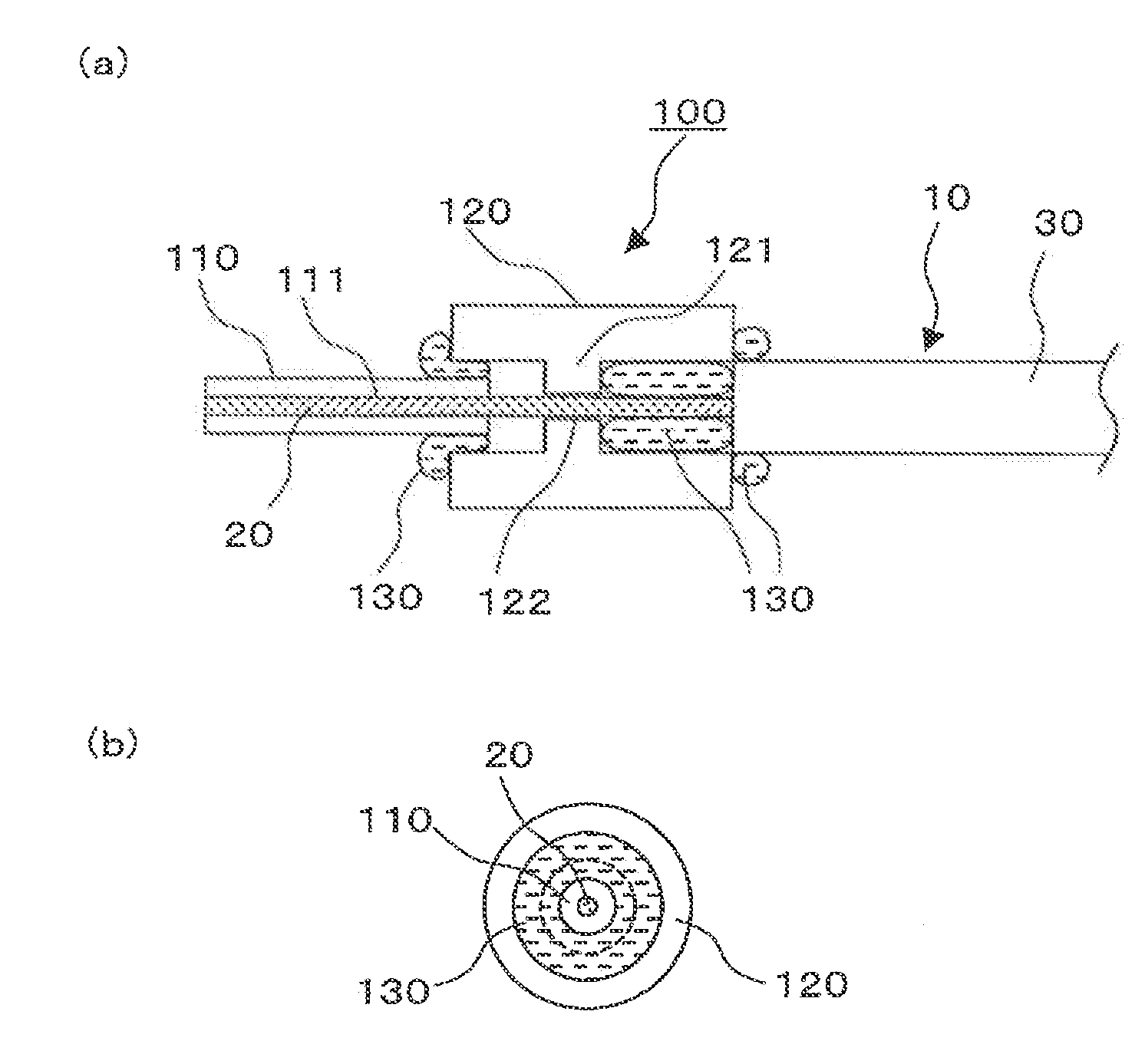
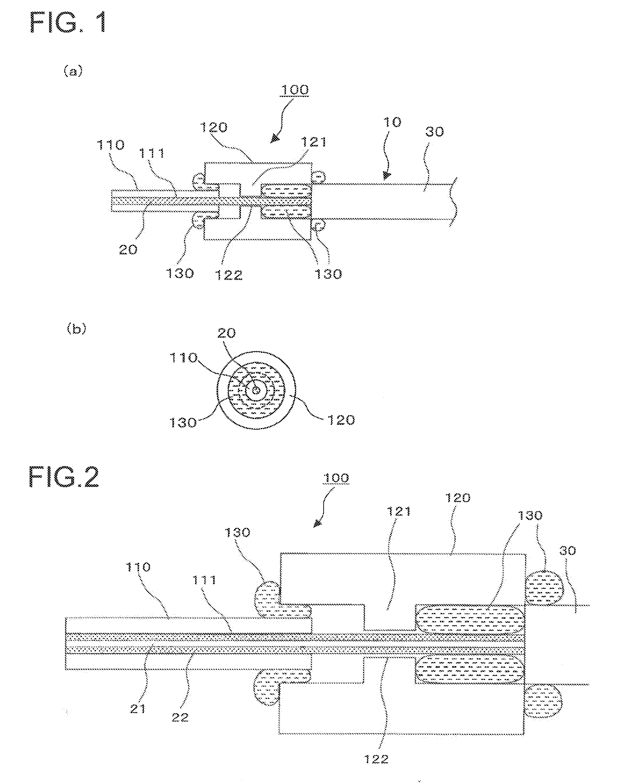
[0122]FIG. 1 is a schematic view showing the configuration of the light input / output terminal module in one of the embodiment of the invention. FIG. 1(a) is a side cross-sectional view of the light input / output terminal module 100 in the embodiment, and FIG. 1(b) is a front view of the input / output terminal module 100 sighted from the left side in the drawing. In this embodiment, an optical fiber is selected as an example of the waveguide in the optical component, and the input / output terminal module of the optical fiber is described.

[0123]In FIG. 1, the optical fiber comprises a glass portion 20 of the fiber as the waveguide and a coating portion 30 of the fiber, an...


PUM


Abstract

A light input/output terminal module 100 comprises a jacket tube 110 and a flange 120. A glass portion 20 of the optical fiber is inserted in the center portion thereof. To efficiently remove the leaked light in a cladding 22 to the jacket tube 110, the jacket tube 110 is made of silica glass or the same material as that of the cladding 22. The jacket tube 110 is fixed by fusion splicing or adhesion to the cladding so as to integrally unify the jacket tube 110 and the cladding 22. The beam diameter at the fiber end portion is enlarged by an optical component which fusion bonds the tip end of the optical fiber to the coreless fiber so that the optical power density at the light input/output terminal module is reduced.

Description

FIELD OF THE INVENTION[0001]The present invention relates to a structure of a light input / output terminal module (optical coupling portion) of the optical components, in particular, relates to a structure of a light input / output terminal module applied to high output optical transmission space coupling optical components. In addition, the present invention relates to a beam converting apparatus for collimating the light or focusing the light, in particular, relates to a beam converting apparatus applied to optical components for a high power optical transmission which enables to broaden the beam diameter at the end portion of the optical fiber.BACK GROUND OF THE INVENTION[0002]Recently, corresponding to the wide spread WDM transmission system enabling a large capacity transmission in an optical communication system, a high output of the used optical power is proceeded. The tendency of the above described optical high output (several W) is enhanced in the future.[0003]In the fabricat...

Claims


Application Information

Patent Timeline
IPC IPC(8): G02B6/36G02B6/32
CPCG02B6/262G02B6/2937G02B6/32G02B6/4296G02B6/3813G02B6/3814G02B6/3861G02B6/327
Inventor WATANABE, SHINGOYAMAGAKI, MIEKOHATANO, TATSUYAMIZUNO, KAZUYOUTANAKA, KANJIFUJISAKI, AKIRA
Owner FURUKAWA ELECTRIC CO LTD
Why Eureka
Try Eureka