Systems and methods for determining a physiological condition using an acoustic monitor

a technology of physiological condition and acoustic monitor, which is applied in the field of systems and methods for determining physiological condition using acoustic monitor, can solve the problems of affecting the accuracy of acoustic monitoring,

Inactive Publication Date: 2009-04-09
JPMORGAN CHASE BANK NA
View PDF107 Cites 698 Cited by
  • Summary
  • Abstract
  • Description
  • Claims
  • Application Information

AI Technical Summary

Benefits of technology

[0070]In another embodiment, the multi-parameter sensor also includes a bonding layer positioned between the frame and the sensing element. In one embodiment, the fra

Problems solved by technology

Many life-threatening conditions are related to heart and respiratory failure.
Heart disease, for instance, has become a leading cause of death, increasing the importance of the clinical technician's ability to recognize abnormal heart conditions.
However, due to the limitations of such equipment, certain sounds are difficult to measure.
Amplifiers in electronic listening equipment are typically not calibrated to properly amplify or attenuate the high voltage sensor signals corresponding to these sounds.
Because this saturation level is less than the correct voltage level of the amplified signal, a portion of the signal will be lost.
Signal clipping can have a detrimental impact on diagnosis and treatment of the patient.
Prolonged loud sounds, such as snoring, may saturate the amplifier for extended periods of time.
Therefore, much data about a patient's breathing pattern may be lost.
However, if the technician is not available to make the gain adjustment, data will be lost.
In addition, even if the technician makes the adjustment, data may be lost immediately before and during the adjustment period.
Setting up several sensors may require a significant amount of time and cause some discomfort to the patient.
In addition, multiple dev

Method used


Image

  • Systems and methods for determining a physiological condition using an acoustic monitor
  • Systems and methods for determining a physiological condition using an acoustic monitor
  • Systems and methods for determining a physiological condition using an acoustic monitor

Examples


Embodiment Construction

[0155]Various embodiments according to the invention will be described hereinafter with reference to the accompanying drawings. These embodiments are illustrated and described by example only, and are not intended to limit the scope of the invention.

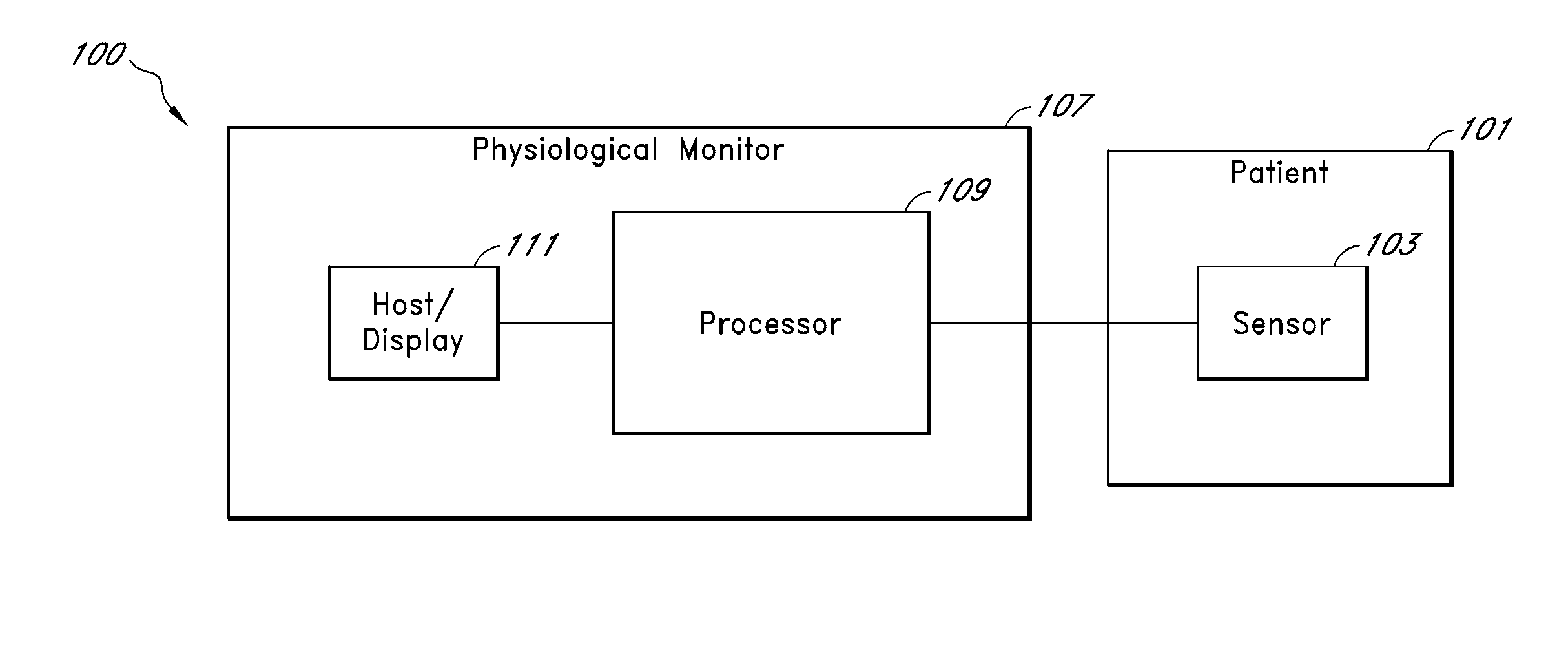
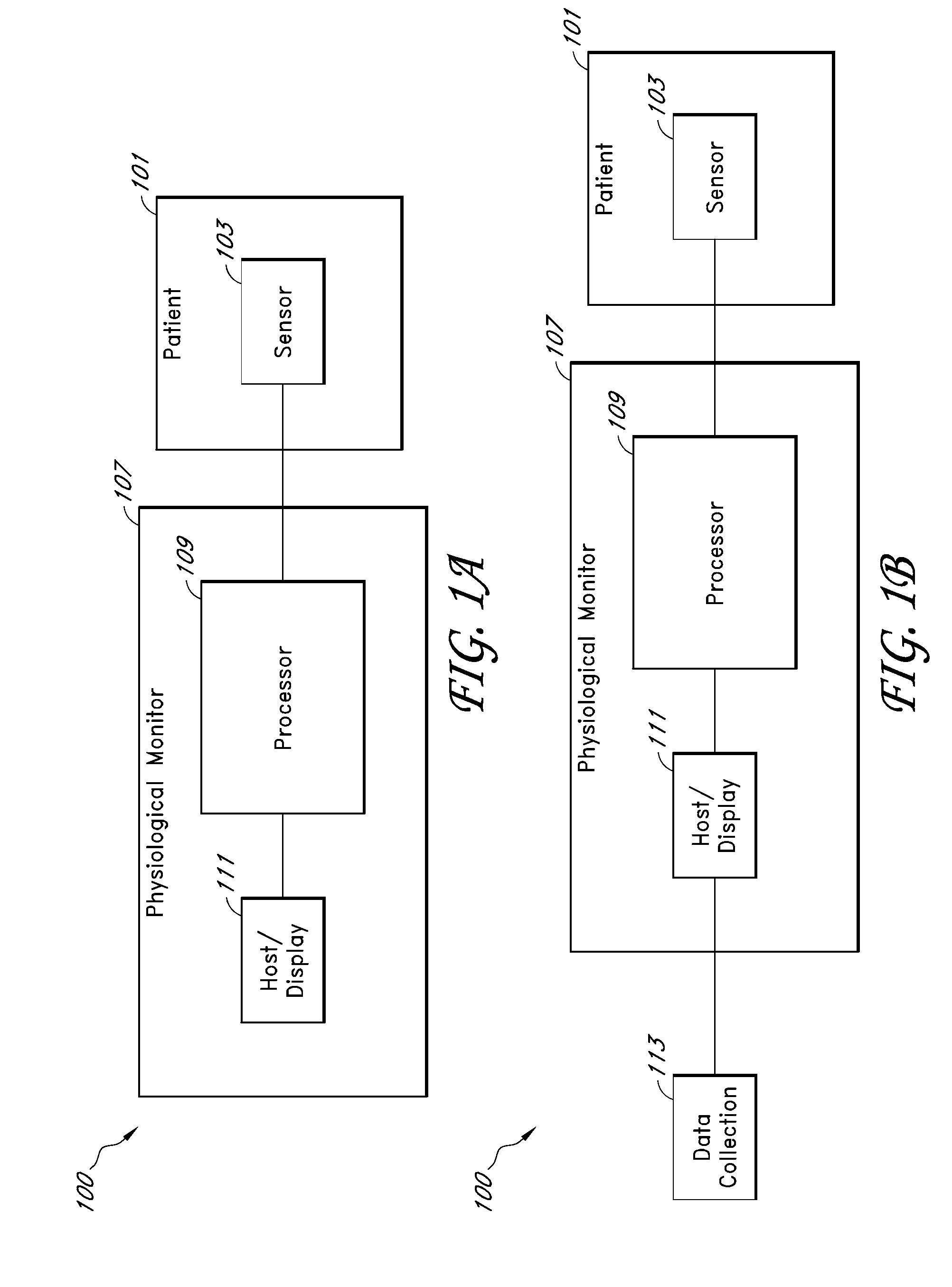
[0156]In various embodiments, a physiological monitoring system comprises or includes an acoustic signal processing system that measures and / or determines any of a variety of physiological parameters of a medical patient. For example, in an embodiment, the physiological monitoring system includes an acoustic respiratory monitor. An acoustic respiratory monitor can determine any of a variety of respiratory parameters of a patient, including respiratory rate, expiratory flow, tidal volume, minute volume, apnea duration, breath sounds, rales, rhonchi, stridor, and changes in breath sounds such as decreased volume or change in airflow. In addition, in some cases the acoustic signal processing system monitors other physiological sounds, such ...


PUM


Abstract

A method of communicating with a physiological sensor is disclosed. In an embodiment, the method includes supplying power through a first conductor in a first mode to the physiological sensor and communicating with an information element through the first conductor in a second mode. The physiological sensor includes the information element, a power supply configured to receive and store power from the first conductor in the first mode, and sensing circuitry configured to receive power from the first conductor in the first mode. The power supply releases the stored power to the sensing circuitry in the second mode.

Description

CROSS-REFERENCE TO RELATED APPLICATIONS[0001]This application claims priority from U.S. Provisional Application No. 60 / 893,853, filed Mar. 8, 2007, titled “Multi-Parameter Physiological Monitor,” which is incorporated herein by reference in its entirety. This application also claims priority from U.S. Provisional Application No. 60 / 893,858, filed Mar. 8, 2007, titled “Multi-Parameter Sensor For Physiological Monitoring,” which is also incorporated herein by reference in its entirety. This application also claims priority from U.S. Provisional Application No. 60 / 893,850, filed Mar. 8, 2007, titled “Backward Compatible Physiological Sensor with Information Element,” which is also incorporated herein by reference in its entirety. This application also claims priority from U.S. Provisional Application No. 60 / 893,856, filed Mar. 8, 2007, titled “Physiological Monitor with Fast Gain Adjust Data Acquisition,” which is also incorporated herein by reference in its entirety.BACKGROUND[0002]1....

Claims


Application Information

Patent Timeline
IPC IPC(8): A61B5/00
CPCA61B5/0002A61B5/0205A61B5/0215A61B5/14552A61B5/0408A61B5/0428A61B5/0402A61B5/25A61B5/30A61B5/318
Inventor TELFORT, VALERY G.LANZO, VICTOR F.WELCH, JAMES P.
Owner JPMORGAN CHASE BANK NA
Why Eureka
Try Eureka