Apparatus and method for measuring vapor flux density

a technology of vapor flux density and apparatus, applied in the direction of optical radiation measurement, instruments, spectrometry/spectrophotometry/monochromators, etc., can solve the problems of most pronounced interference and error in flux measurement, and achieve the effect of improving the utility of eies

Active Publication Date: 2009-04-16
INFICON INC
View PDF3 Cites 7 Cited by
  • Summary
  • Abstract
  • Description
  • Claims
  • Application Information

AI Technical Summary

Benefits of technology

[0012]Benefits and advantages of the present invention include, but are not limited to, improving the utility of EIES for monitoring species flux density in poor and/or variable vacuum conditions or for evaporation processes that require the in

Problems solved by technology

When optical emission from an EIES sensor is measured using a wavelength selection device having a chosen resolution, such as an optical filter or monochromator, as an example, the emissions from common residual gases may int

Method used


Image

  • Apparatus and method for measuring vapor flux density
  • Apparatus and method for measuring vapor flux density
  • Apparatus and method for measuring vapor flux density

Examples


example 1

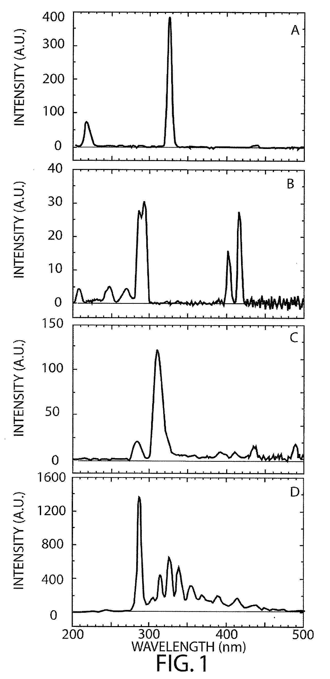
[0040]Using a bandpass filter having a center wavelength at 325 nm and a FWHM (full-width-at-half-maximum) of 10 nm, Cu emission lines were detected at 324.7 and 327.4 nm. The deposition rate measured at the QCM sensor was about 0.25 nm s−1 as shown in FIG. 5A. During the evaporation process, water partial pressure was increased by more than one order of magnitude to 1.5×10⁻⁵ Torr as indicated by the ionization gauge reading shown in FIG. 5B. FIG. 5C shows the output signal from the first chamber of the EIES sensor as a function of time. This measurement is the equivalent of a measurement using an existing EIES sensor. It may be observed that the superposition of the interfering gas signal (from OH) and the Cu flux signal renders the EIES output useless for monitoring the Cu deposition rate. However, with the addition of a second chamber to the EIES sensor, the interfering gas signal can be separately measured as shown in FIG. 5D. The output from the second chamber the two-chamber E...

example 2

[0041]A Ga emission line at 294.4 nm was chosen to demonstrate the effectiveness of the present two-chamber EIES sensor in the presence of interfering gas signal (CO2+ emission bands from 287 to 290 nm) from CO2 present during the deposition, as illustrated in FIG. 6 hereof. The optical filter used for the photo-detection system has a center wavelength at 294.4 nm and a FWHM of 2 nm. The deposition rate at the QCM was about 0.5 nm s−1 (FIG. 6A) with CO2 partial pressures varying between about 5×10⁻⁶ Torr and 9×10⁻⁶ Torr (FIG. 6B). The signals from chamber 1 and chamber 2 are shown in FIGS. 6C and 6D as a function of time. A Ga flux signal, free of interference from CO2 gas, was obtained as shown in FIG. 6E.

[0042]Tests of the present two-chamber EIES sensor have been conducted using partial pressures of various interfering gases in the 10−4 Torr range, the upper pressure limits for the EIES sensor being imposed by pressure limitations on the proper functioning of the thermionic emitt...


PUM

PropertyMeasurementUnit
Electric potential / voltageaaaaaaaaaa
Timeaaaaaaaaaa
Partial pressureaaaaaaaaaa

Abstract

A two-chamber electron impact emission sensor effective for monitoring vapor flux of materials in the presence of interfering species is described. The sensor includes two independent electron excitation regions and one photodetector for monitoring emission from excited species from both chambers. Copper vapor flux from an evaporation source was accurately measured in the presence of interfering H2O vapor, and Ga vapor flux from an evaporation source was accurately monitored in the presence of interfering CO2 gas. The invention permits deposition rates to be monitored using electron-impact emission spectroscopy with significantly improved accuracy in the presence of interfering gases at high partial pressures.

Description

FIELD OF THE INVENTION[0001]The present invention relates generally to apparatus and method for accurate measurement and control of vapor flux density and, more particularly, to an electron-impact emission spectroscopy sensor for measuring vapor flux density of species having reduced interference from background gases and which can be directly correlated to the deposition rate in physical vapor deposition processes.BACKGROUND OF THE INVENTION[0002]Electron-impact emission spectroscopy (EIES) is a versatile technique for monitoring the vapor flux density in a vacuum environment by measuring characteristic photon emission from such species. The EIES technique may monitor multiple materials simultaneously using a single sensor which makes EIES useful for fabricating thin film products such as high-temperature superconductors, compound semiconductor devices, and solar cells, as examples. More specifically, EIES may be used for controlling film composition during co-deposition processes ...

Claims


Application Information

Patent Timeline
IPC IPC(8): C23C14/52C23C14/34
CPCG01J3/443C23C14/544
Inventor LU, CHIH-SHUN
Owner INFICON INC
Why Eureka
Try Eureka