
Transfer System for Forming a Drug Solution from a Lyophilized Drug

a technology of lyophilized drugs and transfer systems, which is applied in the direction of pharmaceutical containers, packaging foodstuffs, packaged goods types, etc., can solve the problems of compromising the precise concentration level of administered drugs, compromising sterility, and difficult to obtain exact volume of diluent to drug ratio,

Inactive Publication Date: 2009-04-16
NOVO NORDISK AS
View PDF4 Cites 67 Cited by
  • Summary
  • Abstract
  • Description
  • Claims
  • Application Information

AI Technical Summary

Benefits of technology

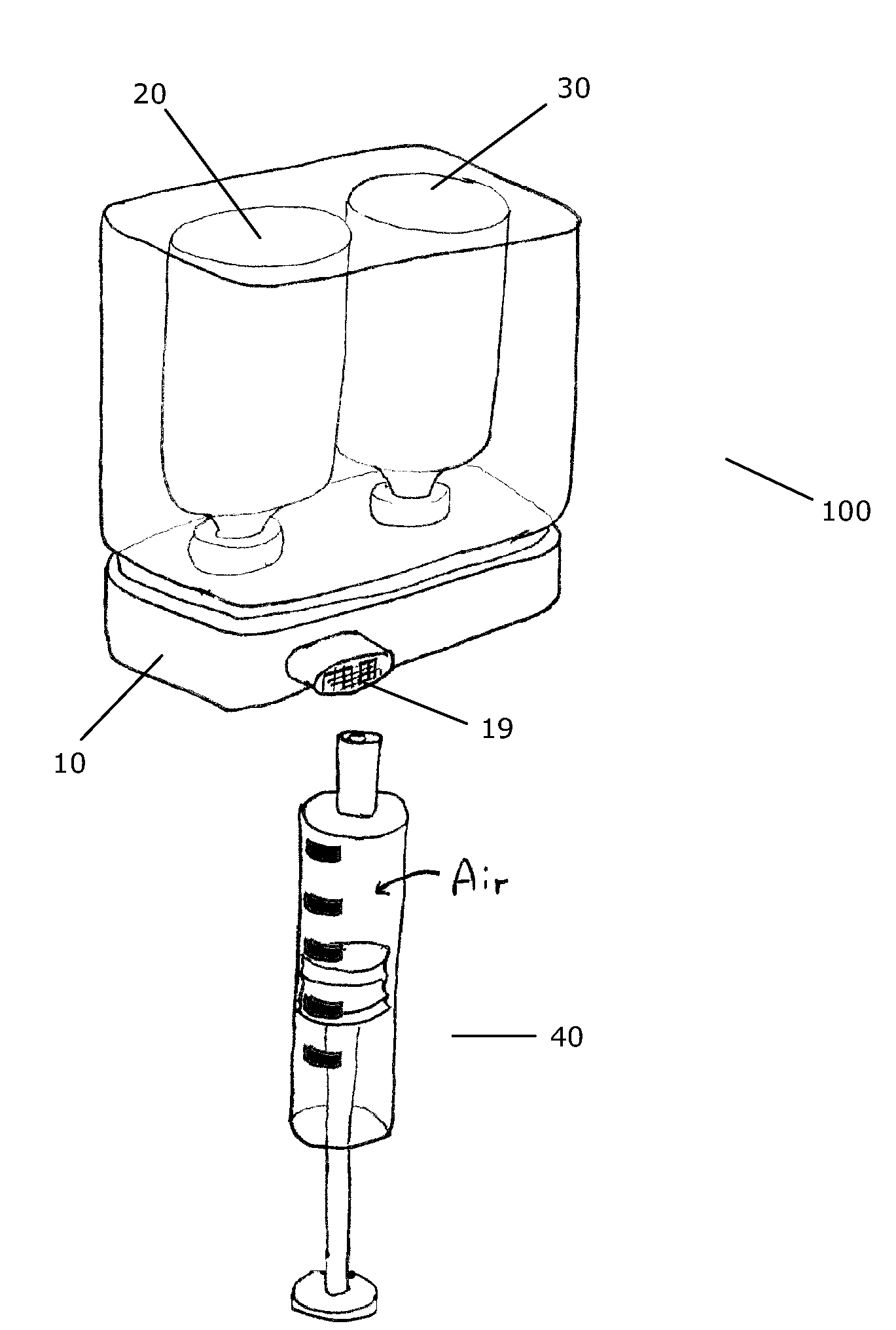
[0010]Having regard to the above-identified problems and deficiencies, it is an object of the present invention to provide a simple but efficient mixing device for mixing the contents of two containers and for transferring the mixed solution to a standard syringe.

Problems solved by technology

When a syringe is used to mix the diluent and drug, the exact volume of diluent to drug ratio is difficult to obtain.
Thus, precise concentration levels of administered drug may be compromised.
Moreover, because the diluent and compound are in separate, sterilized containers, the manual withdrawal of diluent via a syringe and reinjection of the same into the container containing the solid material such as a powdered or lyophilized drug may compromise sterility, and safety due to the use of a syringe.
Reconstituting lyophilized drug from two or more vials in this manner is, however, relatively time consuming.
Furthermore, there is a risk of contamination of the drug due to the number of times a free opening will be exposed to free air or dirt.

Method used


Image

  • Transfer System for Forming a Drug Solution from a Lyophilized Drug
  • Transfer System for Forming a Drug Solution from a Lyophilized Drug
  • Transfer System for Forming a Drug Solution from a Lyophilized Drug

Examples


second embodiment

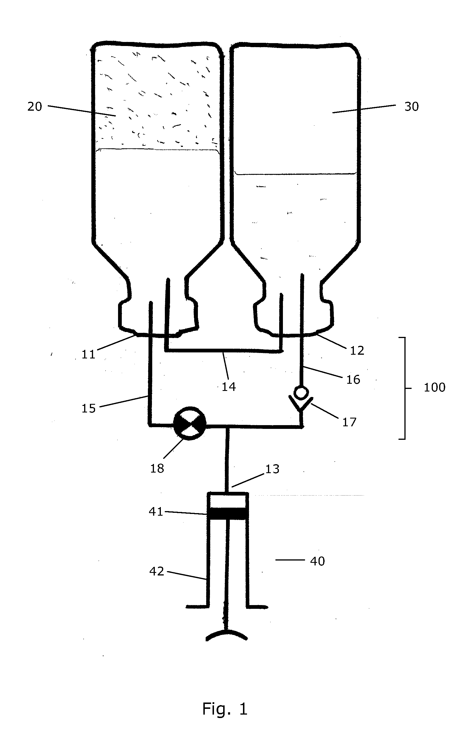
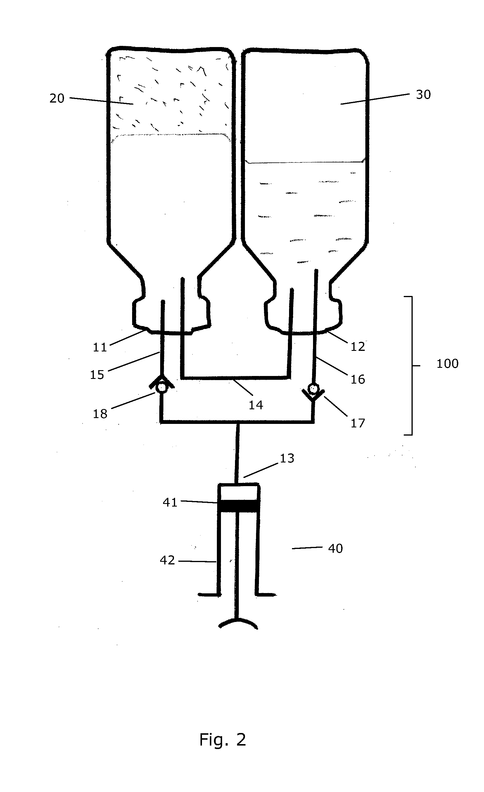
[0118]FIG. 2 is a schematic view of a transfer system 100 according to the invention. The embodiment of FIG. 2 is very similar to the embodiment of FIG. 1, and the fundamental operation of the transfer system 100 will therefore not be described in further detail here.

[0119]In FIG. 2 the second flow control member 18 is an ordinary check valve which is operated by a difference in pressure at the first port 11 and at the third port 13. Accordingly, when the piston 41 of the syringe 40 is pulled back, the second control member 18 will open, and reconstituted drug is transferred from the first container 20 to the syringe 40.

third embodiment

[0120]FIG. 3 is a schematic view of a transfer system 100 according to the invention. The parts of the transfer system 100 of FIG. 3 which are identical to parts which have previously been described with reference to the preceding Figures will not be described in further detail here.

[0121]The transfer system 100 of FIG. 3 may be operated in the following manner. When it is desired to mix the contents of the first container 20 and the contents of the second container 30, it is first ensured that the second flow control member 18 is closed. Then the piston 41 of the syringe 40 is pulled back. This will cause check valve 17 to open while check valve 21 remains closed. Accordingly, liquid is sucked out of the second container 30 and into the syringe 40 via the third channel 16. Furthermore, ambient air is sucked into the second container 30 via filter 22. The check valve 21 ensures that air or material is not sucked from the first container 20 into the syringe 40 during this operation. ...

fourth embodiment

[0124]FIG. 4 is a schematic view of a transfer system 100 according to the invention. The parts of the transfer system 100 of FIG. 4 which are identical to parts which have previously been described with reference to the preceding Figures will not be described in further detail here.

[0125]The transfer system 100 of FIG. 4 may be operated in the following manner. When it is desired to mix the contents of the first container 20 and the contents of the second container 30, air is initially sucked into the syringe 40 by pulling the piston 41 back, and the syringe 40 is then coupled to the third port 13. Then the piston 41 is pushed forward. This causes check valve 17, 18 to open, and air is transferred from the syringe 40 into the second container 30 via channel 16, thereby increasing the pressure in the second container 30. The increased pressure in the second container 30 causes the second contents to be transferred from the second container 30 to the first container 20, via the first...


PUM


Abstract

A transfer system (100, 100′, 100″) adapted to allow first contents of a first container (20) and second contents of a second container (30) to mix to form a material. The mixed material is retrieved to a syringe (40). The transfer system (100, 100′, 100″) comprises first (17) and second (18) flow control members for controlling fluid flow between the containers (20, 30) and the syringe (40). The invention further relates to a drug mixing kit comprising a container unit containing first and second containers, and a transfer unit comprising ports for receiving the containers and a syringe and a number of flow channels. The container unit and the transfer unit are adapted to be coupled together to form a drug mixing kit.

Description

[0001]The present invention relates to the preparation and administration of a product and, more particularly, to the injection of the same into a living organism, for example, a human body.BACKGROUND OF THE INVENTION[0002]Previously, various devices have been developed for the percutaneous delivery of medications into living organisms including syringes in which a liquid is delivered from a chamber using pressure asserted by a manual plunger through a needle inserted under the skin.[0003]Additionally, it is well known in the art that the storage life of certain injectable substances such as glucagon, used to dissolve blood clots, is increased when the substance is stored in a powdered or lyophilized state, for example. These lyophilized substances (i.e., drugs or compounds) are presently used for injection of materials that would otherwise be unstable. Lyophilization, for example, is the rapid freezing of a material at a very low temperature followed by rapid dehydration by sublima...

Claims


Application Information

Patent Timeline
Patent Type & Authority Applications(United States)
IPC IPC(8): A61M5/31
CPCA61J1/2089A61J1/2096A61J2001/2013A61J2001/2017A61J2001/2037A61M5/1782A61J2001/2062A61J2001/2072A61J2001/2075A61J2001/2082A61J2001/2086A61J2001/2058A61J1/2017A61J1/2075A61J1/2086A61J1/2062A61J1/2072A61J1/2082A61J1/2037A61J1/2013A61J1/2058A61J1/201
Inventor RADMER, BO
Owner NOVO NORDISK AS
Learn More