Hybrid drive device

a drive device and hybrid technology, applied in the direction of electric propulsion mounting, jet propulsion mounting, gearing, etc., can solve the problems of large coupling portions, complicated exterior shape of the case, and the support structure of the rotary electrical machine described above. , to achieve the effect of compact exterior shape and simple exterior shap

Inactive Publication Date: 2009-04-23
AISIN AW CO LTD
View PDF32 Cites 60 Cited by
  • Summary
  • Abstract
  • Description
  • Claims
  • Application Information

AI Technical Summary

Benefits of technology

[0009]Accordingly, an object of the present invention is to obtain a hybrid drive device in which a transmission is supported by a rotary electrical machine case provided on an engine side, and by which the rotary electrical machine case, as well as the entire device, can have a relatively simple exterior shape and can be made compactly.

Problems solved by technology

However, the support structure for the rotary electrical machine described above has a problem.
Thus, large coupling portions are required.
However, when adopting such a structure, the rotary electrical machine case itself consists of a plurality of members, which causes the shape of a case exterior to become complicated, and the size of the device becomes large at the same time, which is unfavorable.

Method used


Image

  • Hybrid drive device
  • Hybrid drive device
  • Hybrid drive device

Examples


Embodiment Construction

[0038]Hereinafter, an exemplary embodiment regarding a hybrid drive device HV according to this application will be explained based on the drawings.

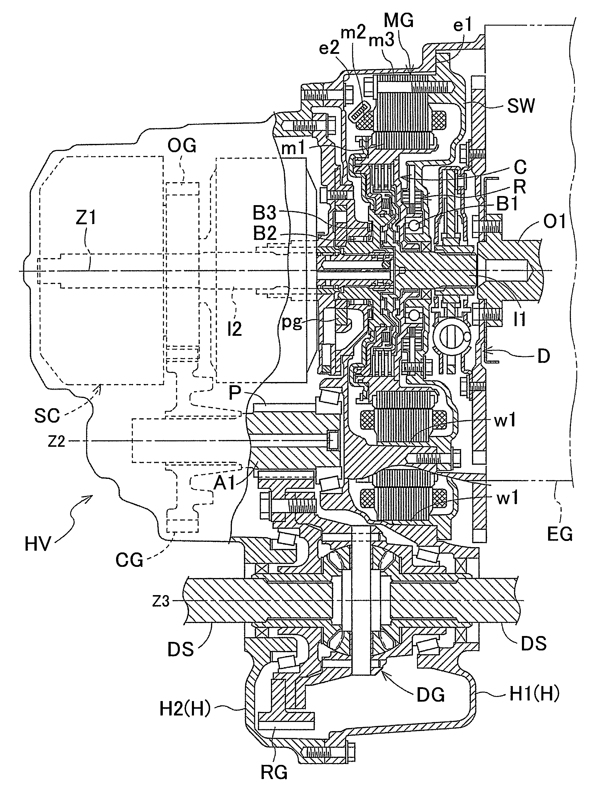
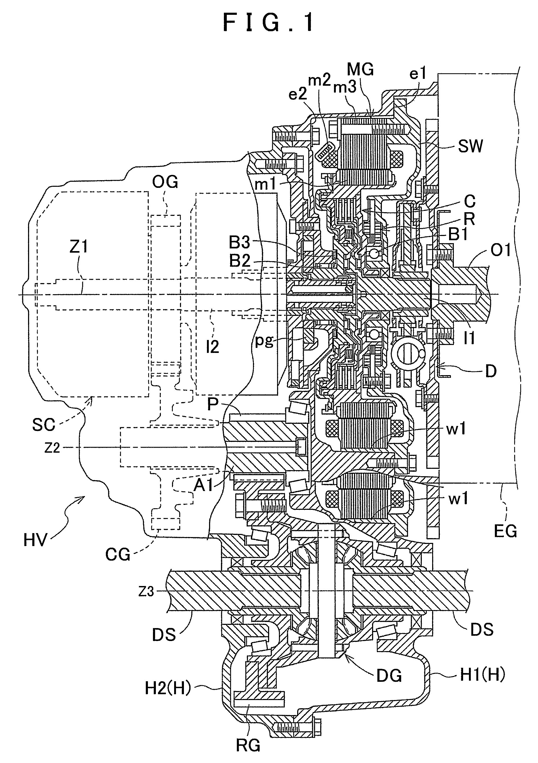
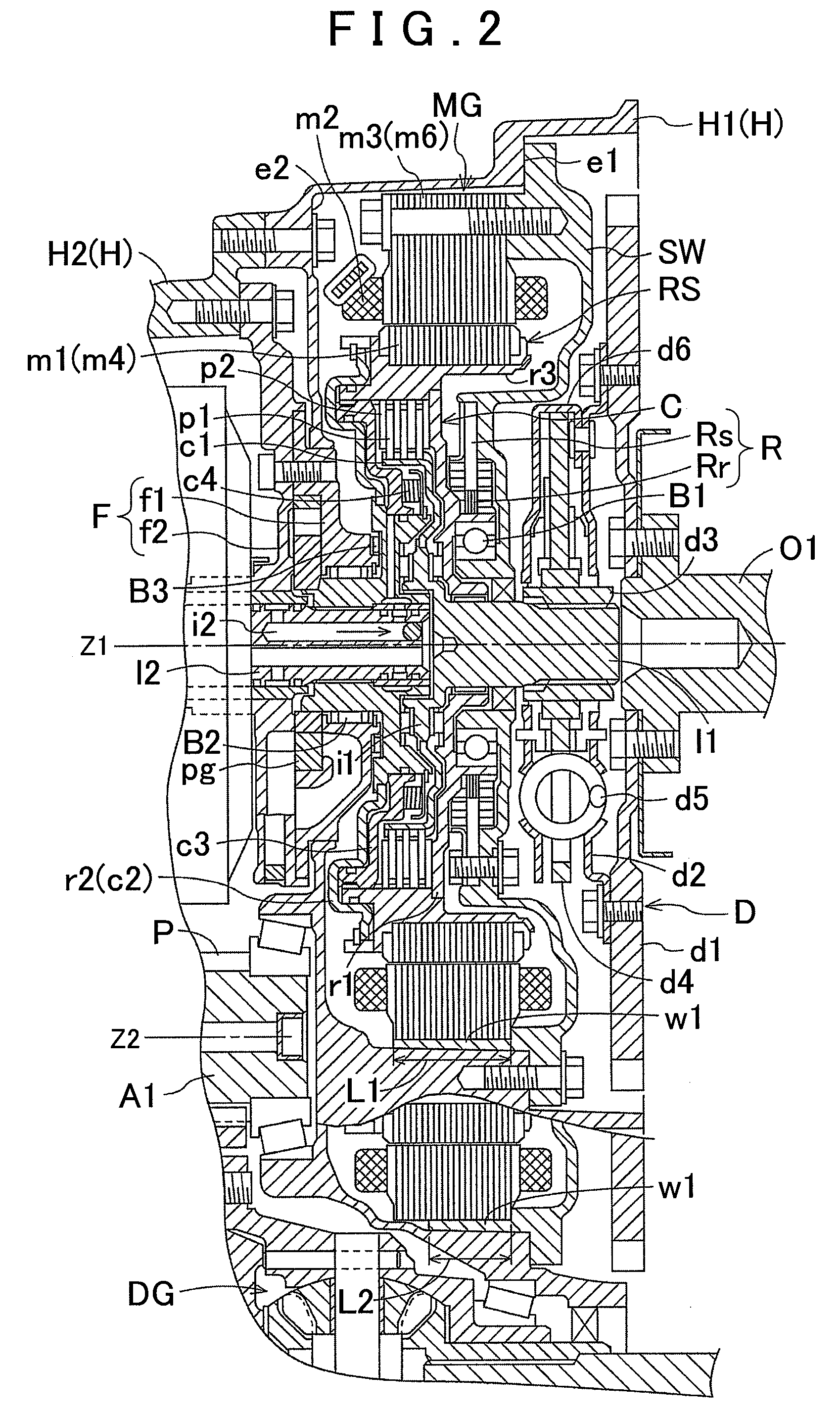
[0039]FIG. 1, FIG. 2 are cross-sectional views showing a structure of the hybrid drive device HV, FIG. 3 is an explanatory view showing a state of assembling operation of the hybrid drive device HV, FIG. 4 is a view showing an arrangement structure of main devices viewed in an axial direction, and FIG. 5 is a schematic view of a drive transfer system adopted in this hybrid drive device HV.

[0040]A vehicle including this hybrid drive device HV has an engine EG and a rotary electrical machine MG as drive sources, and the vehicle shifts rotary drive obtained therefrom with a transmission SC, and transfers shifted output to driving wheels W via a counter gear CG and a differential gear DG so as to travel.

[0041]As shown schematically, in FIG. 5, the rotary electrical machine MG is drive-coupled to the transmission SC, and the engine EG is driv...


PUM


Abstract

A hybrid drive device including a drive device input shaft coupled to an engine, a rotary electrical machine, a transmission shifting and outputting rotary drive transferred from the rotary electrical machine or the drive device input shaft or the both of them, a transmission case accommodating the transmission, and a rotary electrical machine case having a joint surface joining with the transmission case, a step portion with a diameter which is reduced when seen from an input shaft input end side is provided in an inner peripheral portion of the rotary electrical machine case, and a partition wall supporting the rotary electrical machine from the input shaft input end side is fixed to the step portion.

Description

INCORPORATION BY REFERENCE[0001]This Application claims priority from Japanese Patent Application No. 2007-272814, filed on Oct. 19, 2008, the disclosure of which, including the specification, drawings and abstract, is incorporated herein by reference in its entirety.BACKGROUND OF THE INVENTION[0002]1. Field of the Invention[0003]The present invention relates to a hybrid drive device which includes as drive sources an engine (for example, an internal combustion engine such as a gasoline engine, a diesel engine, or the like) and a rotary electrical machine (including, for example, a motor which receives supply of power to generate driving force (for example, rotational driving force), a generator which receives a supplied driving force to generate power, or a machine that works as a motor or generator selectively according to the operation state), and is structured to obtain driving force from one or both of the engine and the rotary electrical machine, shift the driving force with a...

Claims


Application Information

Patent Timeline
Patent Type & Authority Applications(United States)
IPC IPC(8): F16H37/08F16H57/02F16H57/04B60K6/26B60K6/387B60K6/40B60K6/405B60K6/48B60K6/547B60K11/02B60K17/04B60L50/16
CPCY02T10/6221Y10T74/2189B60K6/26Y10T74/2186B60K6/387B60K6/405B60K5/04B60K6/48Y02T10/62
Inventor SANJI, HIROAKIIKE, NOBUKAZU
Owner AISIN AW CO LTD
Why Eureka
Try Eureka