Analyte collection chip

a technology of analyte and chip, which is applied in the field of biochips, can solve the problems of difficult needle inserting into the vein, inability to collect blood without an environment, and high cost of carrying out tests, and achieve the effect of convenient collection of analyte from a living body and efficient introduction of blood

Inactive Publication Date: 2009-04-23
ROHM CO LTD
View PDF8 Cites 26 Cited by
  • Summary
  • Abstract
  • Description
  • Claims
  • Application Information

AI Technical Summary

Benefits of technology

[0014]In the following, the analyte is, for example, blood, and the subject to be tested is a living body. When blood is collected from a subject to be tested, the chip is pressed so that the thin portion of the chip directly contact the skin of the subject to be tested. Then the skin of the subject being tested is pierced with a needle via the thin portion, and bleeding is caused. At this time, the blood pressure within the veins has a higher pressure than the interior of the chip. Therefore, the total quantity of the blood released flows directly into the interior of the analyte inlet portion via the thin portion. Therefore, it is possible to save the trouble of collecting the blood from the skin using a hypodermic syringe or the like, and placing the collected blood into the chip, so it is possible to easily collect and analyze blood. Also, blood does not remain on the skin after collecting the blood. Therefore, it is possible to keep the skin clean after collecting the blood.
[0022]According to the chip of the present invention as described above, it is possible to easily collect analyte from a living body.

Problems solved by technology

Therefore, if for example the person being tested is inexperienced, it is difficult to insert the needle into the vein.
Therefore, blood cannot be collected without an environment in which all these devices are provided.
Therefore, carrying out tests is expensive, and at the same time the places where blood can be collected are limited.
Also, in the method according to U.S. Pat. No. 4,883,767, it is difficult to efficiently inject the extracted capillary blood into the blood inlet portion of the biochip.
If this method is used, capillary blood adheres to the internal walls of the dropping pipette, so it is not possible to use all the extracted capillary blood in the test.

Method used


Image

  • Analyte collection chip
  • Analyte collection chip
  • Analyte collection chip

Examples


first embodiment

(1) Structure

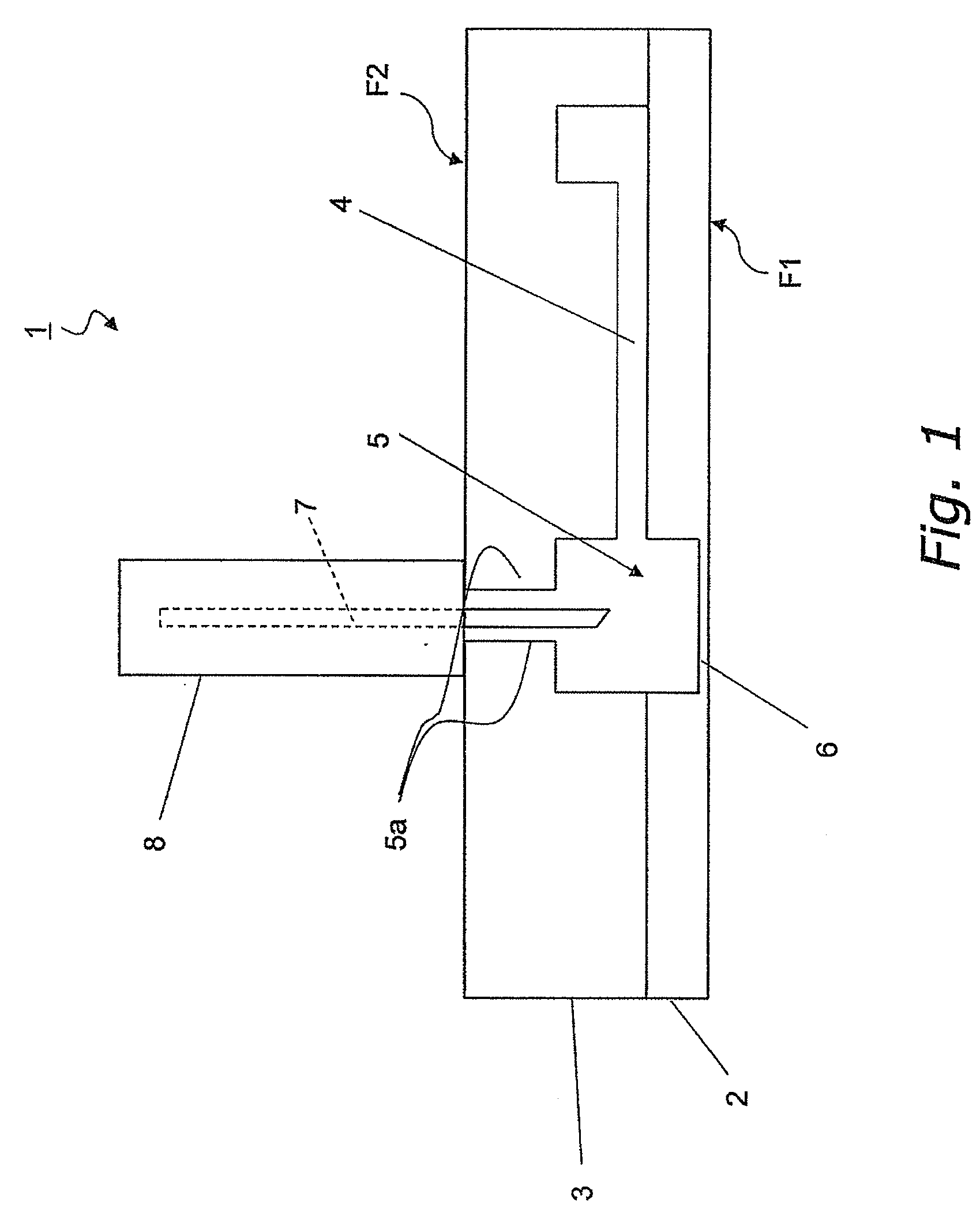
[0031]FIG. 1 is a structural diagram of a chip according to a first embodiment of the present invention. As shown in FIG. 1, a chip 1 is formed by for example bonding together two thin plate shaped substrates 2 and 3. Here, in the chip, the contact surface with the living body is called the first surface F1, and the surface opposite to the first surface F1 is called the second surface F2. The material of the substrates 2 and 3 may be for example the organic compounds indicated below, or inorganic compounds such as glass, silicon, or metal. The organic compounds can include polyethylene terephthalate (PET), polydimethylsiloxane (PDMS), polymethyl methacrylate (PMMA), polycarbonate (PC), polypropylene (PP), polystyrene (PS), poly vinyl chloride (PVC), polysiloxane, allyl ester resin, cycloolefin polymer, ST rubber, and so on.

[0032]The chip 1 has an analyte inlet portion 5, which is an internally formed space, into which analyte is introduced. The chip 1 has a thin portion...

second embodiment

[0044]FIG. 4 is a structural diagram of a chip 101 according to a second embodiment. The chip 101 is formed by bonding together thin plate-shaped substrates 102 and 103. In the chip 101, the contact surface with the living body is called the first surface F1, and the surface opposite to the first surface F1 is called the second surface F2. The chip 101 includes an analyte inlet portion 105, and a thin portion 106. The analyte inlet portion 105 is a space formed within the substrates 102 and 103 into which analyte is introduced. The thin portion 106 is formed on the first surface F1 side of the chip 101, and partitions the space forming the analyte inlet portion 105 from the external space. Also, the thin portion 106 includes a film 109. The film 109 is formed on a part of the substrate 102 that is formed thinner than other parts. The film 109 is provided to ensure greater adhesion between the first surface F1 of the chip 1 and the skin of the living body. The film 109 is disposed in...

third embodiment

(1) Constitution

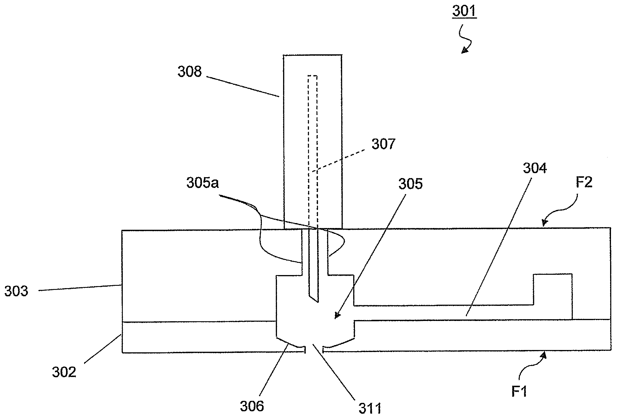
[0052]FIG. 5 is a structural diagram of a chip 201 according to a third embodiment. The chip 201 is formed by bonding together thin plate-shaped substrates 202 and 203. In the chip 201, the contact surface with the living body is called the first surface F1, and the surface opposite to the first surface F1 is called the second surface F2. The chip 201 includes an analyte inlet portion 205 and a film 209. The analyte inlet portion 205 is a space formed within the substrates 202 and 203, into which analyte is introduced. Also, an aperture 210 is formed in the first surface F1 of the chip 201 through which the analyte inlet portion 205 is exposed. The aperture 210 is formed in at least apart of the first surface F1 that contacts the living body.

[0053]The film 209 is formed to cover the aperture 210. The film 209 is provided to ensure greater adhesion between the first surface F1 of the chip 201 and skin of the living body. The thickness of the film 209 may be a thicknes...


PUM


Abstract

To provide a chip for collecting analyte from a living body. Specifically, the chip includes a thin plate-shaped main body, an analyte inlet portion, and a thin portion. Analyte is introduced into the analyte inlet portion, which is formed within the main body. The thin portion partitions the space forming the analyte inlet portion from the external space. According to the chip of the present invention, it is possible to eliminate the time for collecting analyte from a living body using a hypodermic syringe or the like, and placing the collected analyte into the chip. Also, the chip according to the present invention does not leave analyte remaining at the position from which the analyte was extracted, so after the test the position where the analyte was extracted from the living body is clean.

Description

CROSS-REFERENCE TO RELATED APPLICATION[0001]This U.S. National stage application claims priority under 35 U.S.C. § 119(a) to Japanese Patent Application No. 2005-237201, filed in Japan on Aug. 18, 2005, the entire contents of which are hereby incorporated herein by reference.BACKGROUND OF THE INVENTION[0002]1. Field of the Invention[0003]The present invention relates to a biochip that carries out biochemistry tests for DNA, cells, proteins, immunity, and so on. More particularly the present invention relates to a chip for collecting analyte from a living body.[0004]2. Background Information[0005]Blood tests are frequently carried out, such as for periodic health examinations, tests in hospitals, tests for doping of athletes, and so on. The method of collecting blood in normal blood tests is to insert a hypodermic syringe having a hollow needle into a protruding vein on an arm to which a tourniquet has been applied, and to withdraw the piston of the syringe to take the blood sample. ...

Claims


Application Information

Patent Timeline
Patent Type & Authority Applications(United States)
IPC IPC(8): A61B5/15A61M37/00A61M5/42
CPCA61B5/1411A61B10/0045A61B17/205G01N2035/00158A61B2010/0009G01N33/491A61B2010/0006A61B5/150022A61B5/150358A61B5/150412A61B5/150503A61B5/150969A61B5/15105A61B5/15107A61B5/15117A61B5/15142
Inventor MOMOSE, SHUNSHIMASAKI, TAKAAKI
Owner ROHM CO LTD
Why Eureka
Try Eureka