Implantable and lumen-supporting stents and related methods of manufacture and use

a technology of stents and lumens, applied in the field of implantable medical devices, can solve the problems of reducing the service life of the stent, unable to meet the exactness of the actual stent, and the specific material properties assigned to the modeled stents based on these commercial stents, so as to improve the lateral bending characteristics, improve the service life, and enhance the deflection characteristics

Inactive Publication Date: 2009-04-23
MEDLOGICS DEVICE CORP
View PDF20 Cites 163 Cited by
  • Summary
  • Abstract
  • Description
  • Claims
  • Application Information

AI Technical Summary

Benefits of technology

[0014]One aspect of the present disclosure provides a stent system with an improved stent. According to one embodiment, the stent includes improved expansion characteristics. According to another embodiment, the stent includes improved lateral bending characteristics. In one particular embodiment, the stent undergoes lateral or radial deflection with strain distribution primarily at transition regions between struts and crown shoulders on opposite sides of crown peaks of the stent's filamental pattern. In another embodiment, the stent includes geometry along crown regions that differ from strut geometry, providing enhanced deflection characteristics in combination with enhanced characteristics along the strut, such as for example for drug delivery or visibility.
[0024]In another embodiment, the low strain region comprises at least one of (a) a width in a circumferential plane around the longitudinal axis that is substantially greater than a width of the high strain region along the longitudinal axis, (b) a width that is substantially greater than a radial thickness at the respective low strain region, and (c) a substantially increased radiopacity versus the high strain region.
[0028]Various additional modes, embodiments, features, and variations are also contemplated with respect to these various aspects and modes, providing still further benefit and utility.

Problems solved by technology

It is noted however to make clear, the estimated dimensions and specific material properties assigned to the modeled stents based upon these commercial stents likely do not match those actual stents with perfect accuracy.
Thus, this study, and results and conclusions made, relate only to “estimated models” considered to have certain “similarities” with these commercial stents, but do not directly represent those actual commercial stents or their manufacturers, nor capture or represent their actual characteristics or performance.
Conversely, if the width of the struts of that model #1 were uniform at the crown peaks with same increased width vs. radial thickness as along the struts, the expansion characteristics would likely be altered, such as for example: requiring higher inflation pressure to produce similar strain at the crowns necessary for expansion; potential for higher recoil; and possibly adverse consequences of twisting of the crowns out of plane when straining a planar structure of higher width than thickness in the circumferential plane.

Method used


Image

  • Implantable and lumen-supporting stents and related methods of manufacture and use
  • Implantable and lumen-supporting stents and related methods of manufacture and use
  • Implantable and lumen-supporting stents and related methods of manufacture and use

Examples


example 1

I. INTRODUCTION

[0193]Certain aspects of exemplary stent constructions consistent with the present embodiments were modeled using 3-Dimensional Finite Element Analysis (3-D FEA). These 3-D FEA models were subjected to certain simulated deflection forces in order to calculate, represent, and evaluate material strain distributions variously within and between representative stent segments of the models under conditions related to radial expansion and lateral bending, respectively.

[0194]Similar 3-D FEA modeling and simulation was performed for two additional stent designs intended to represent certain commercially available stents. More specifically, these two additional stent models were intended to represent certain aspects of two cobalt-chromium stents of different designs, and from two different manufacturers, and that represent the top selling bare metal stents in the world: the “DRIVER®” stent commercially sold by Medtronic, and the “VISION®” stent commercially sold formerly by G...

example 2

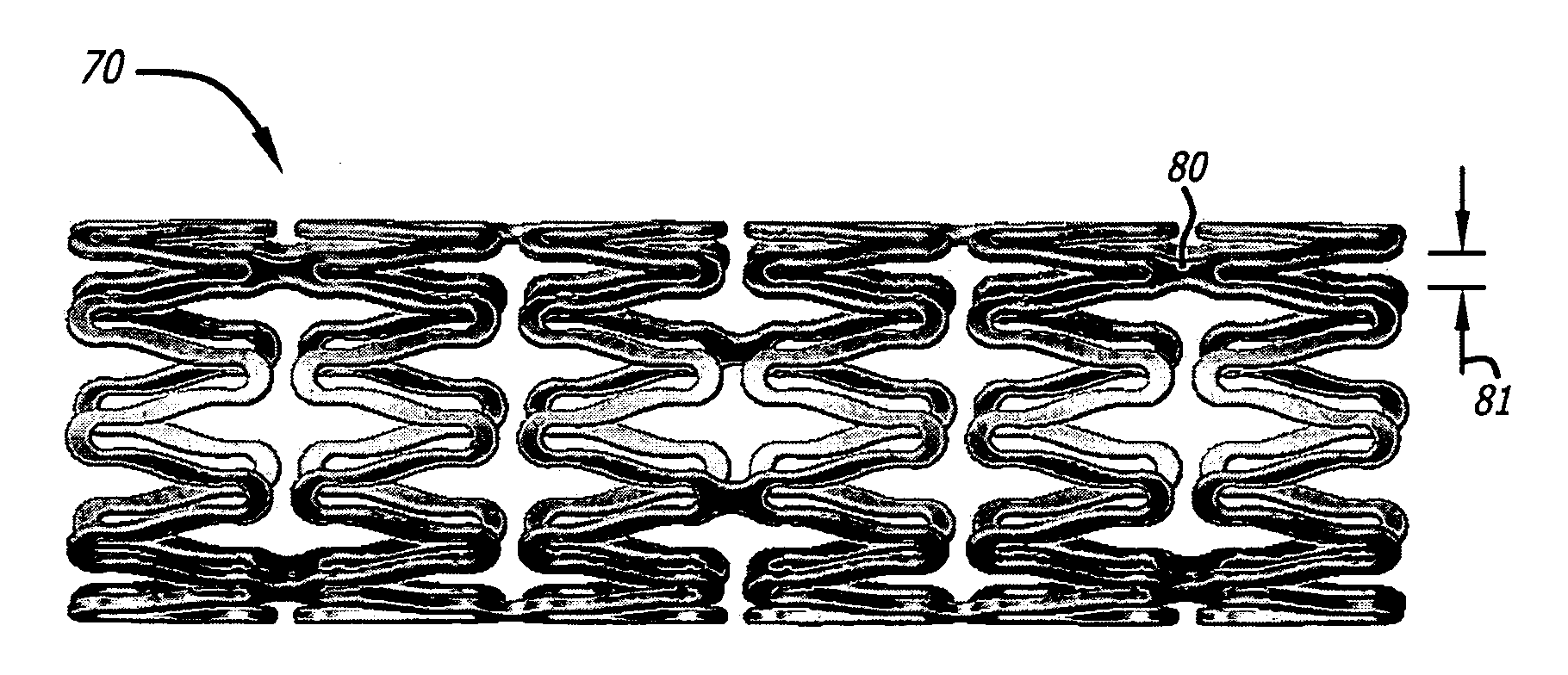
[0239]Twenty pigs underwent coronary artery placement of 22 stents of two types as follows: commercially available Driver® stents (n=10); and a physical embodiment similar to that described above with respect to FIGS. 2A-D, referred to here as “Model #2” (n=12) as incorporating similar features as presented for Model #2 in Example #1 simulations presented above. Stents used from each group were provided for intended use in 3.0 mm or 3.5 mm diameter sizes, and were all 18 mm in length. Average vessel diameter at implant was 2.89 mm for the Model #1 group, and 3.04 mm for the Driver® group.

[0240]At day 28, animals were re-studied for angiographic endpoints variously represented in Tables 2A-4B. Certain criteria were measured or calculated and included in these Tables as follows. “Balloon-to-Artery” ratio is a measure of balloon oversizing as related to reference vessel diameter at the time of implant. “Acute gain” is the increase in vessel diameter due to stenting, measured immediatel...


PUM


Abstract

An implantable stent includes multiple circumferential segments that surround a bore and are connected in series along a length to form a tubular wall. Multiple adjacent alternating opposite facing crowns arranged along each segment's circumference are bridged by struts. The struts include a series of staggered arcuate edges with limited flats to provide a limited region of maximum width between significantly extended reducing diameter tapers at either end where they transition into the crowns. Connections between adjacent segments are wider and stiffer than the struts and strut-crown transitions in the segments. The crowns include inner and outer radii with off-set centers along a common axis to provide medial crown peaks along the axis that are wider than the narrowed crown shoulders on either side of the axis and from which the tapered struts extend. Material strain and flexure along the stent during lateral bending is distributed mainly within the segments, e.g. along the struts or crowns, versus at the connections between segments. Material strain and deformation during radial expansion is principally concentrated at the crown shoulders and tapered transition region with the struts. Particular closed-open-closed arrangements along the stent length are disclosed, though with fewer stent connections in the relatively “closed” end-portions along the stent than are provided by other typically “open” cell stents in prior use. Enhanced combinations of performance characteristics are provided regarding visibility, trackability, expansion characteristics, fatigue failures, coating integrity, and local drug delivery from the stent.

Description

CROSS REFERENCE TO RELATED APPLICATIONS[0001]The present application claims the benefit under 35 U.S.C. §119(e) of U.S. Provisional Patent Applications No. 60 / 981,433 filed Oct. 19, 2007 which is incorporated by reference herein in its entirety.FIELD OF THE INVENTION[0002]This invention relates to implantable medical devices. More specifically, the invention relates to implantable and lumen-supporting stents. Still more specifically, it relates to such stents for the treatment or inhibition of stenoses in coronary or peripheral vessels in humans.BACKGROUND OF THE INVENTION[0003]Cardiovascular disease, including atherosclerosis, is the leading cause of death in the United States. The medical community has developed a number of methods and devices for treating coronary heart disease, some of which are specifically designed to treat the complications resulting from atherosclerosis and other forms of coronary vessel narrowing.[0004]An important development for treating atherosclerosis a...

Claims


Application Information

Patent Timeline
Patent Type & Authority Applications(United States)
IPC IPC(8): A61F2/06
CPCA61F2/91A61F2/915A61F2230/0054A61F2002/91558A61F2002/91575A61F2002/91541A61F2230/0069A61F2250/0018A61F2250/0029A61F2250/0032A61F2250/0036A61F2210/0014A61F2210/0076A61F2250/0031A61F2250/0068
Inventor LEE, MICHAEL J.KARI, STUART EARLKING, RILEY
Owner MEDLOGICS DEVICE CORP
Why Eureka
Try Eureka