

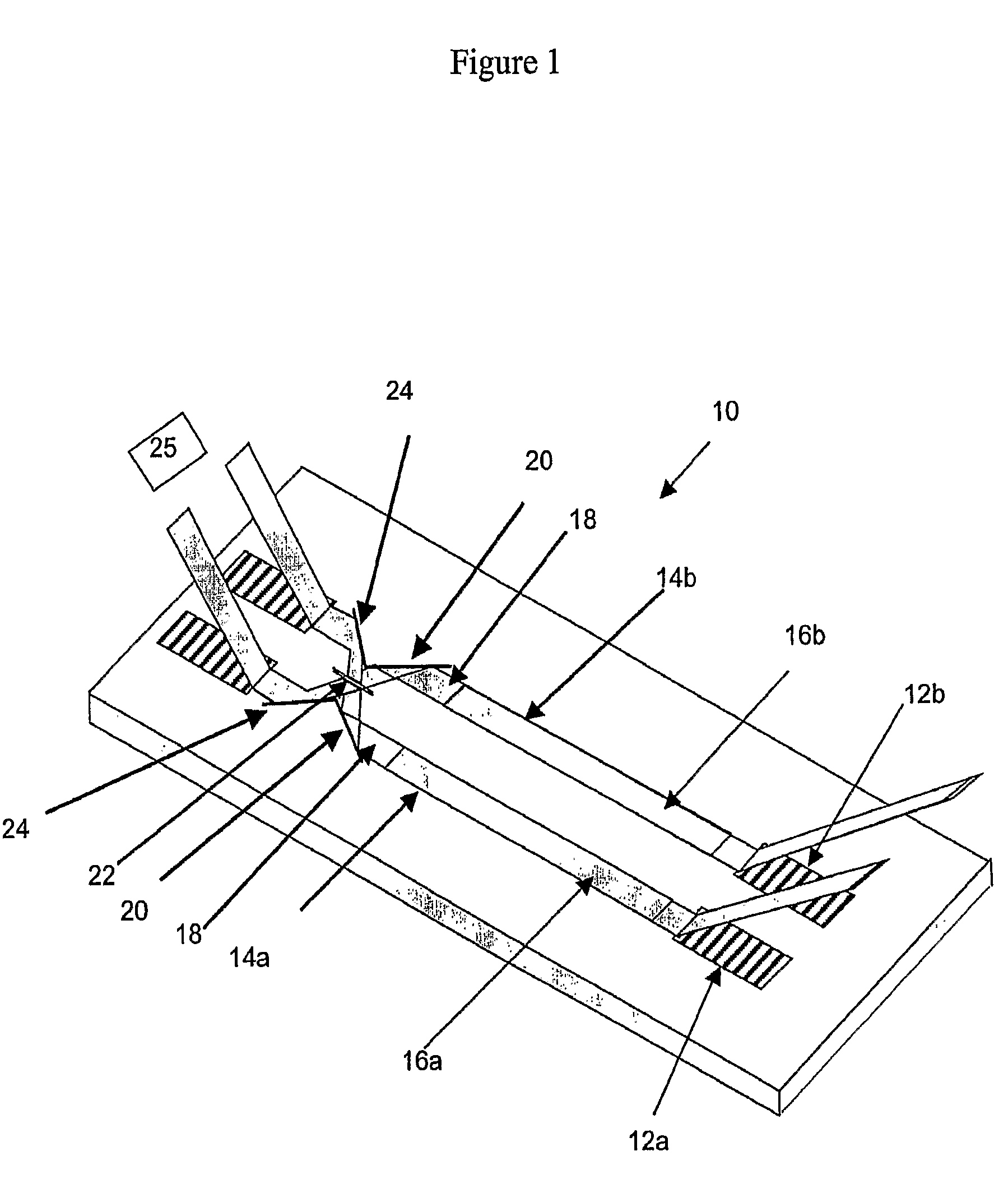
Method and apparatus for enhancing waveguide sensor signal
a waveguide sensor and waveguide technology, applied in the field of methods and apparatus for enhancing waveguide sensor signals, can solve the problems of insufficient sensitivity of designs produced to date, failure to yield a detectable response, etc., and achieve the effect of improving the sensitivity of an order of magnitud
- Summary
- Abstract
- Description
- Claims
- Application Information
AI Technical Summary
Benefits of technology
Problems solved by technology
Method used
Image

Examples
examples
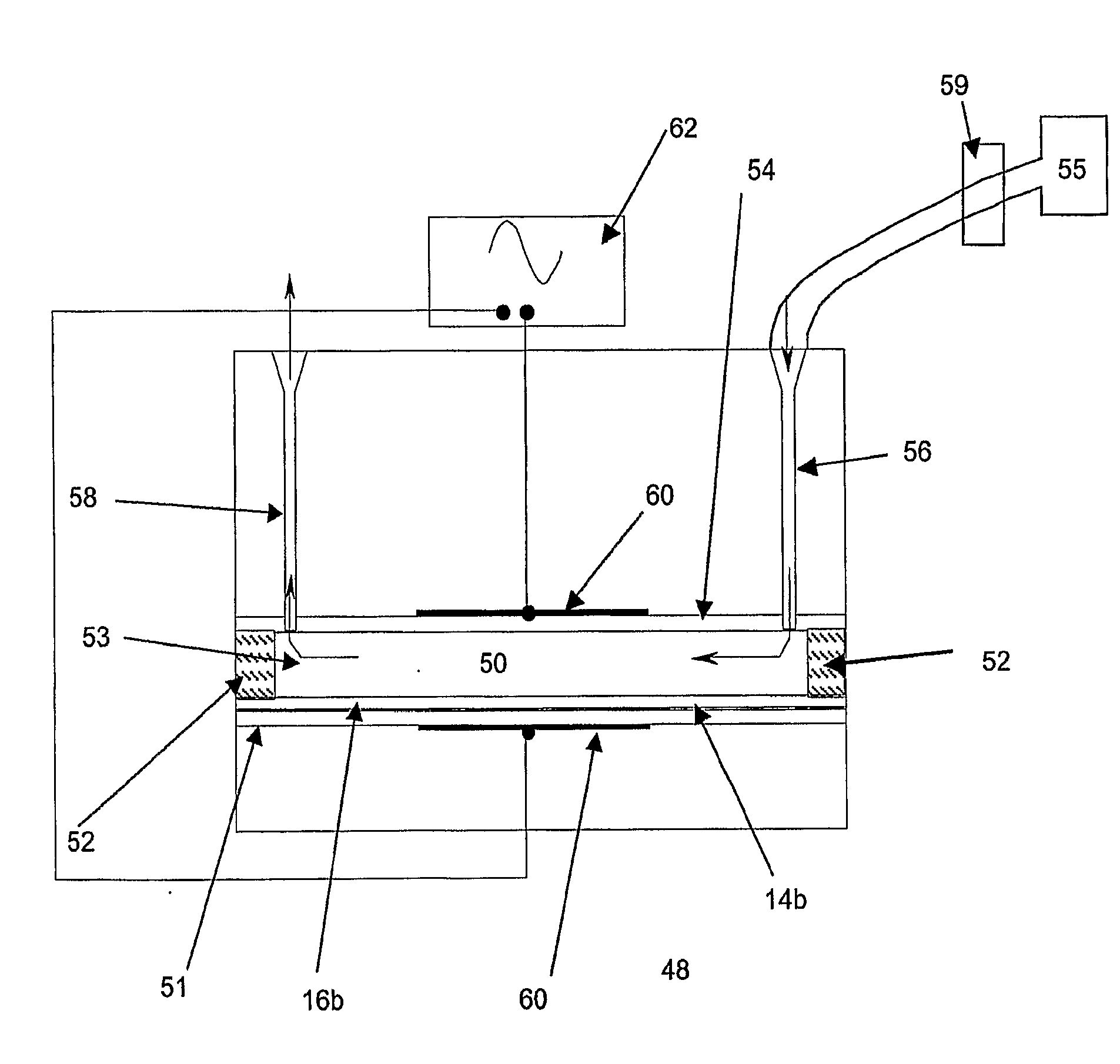
Guided Wave Phase Modulation by E-Field and Magnetic Field Applications
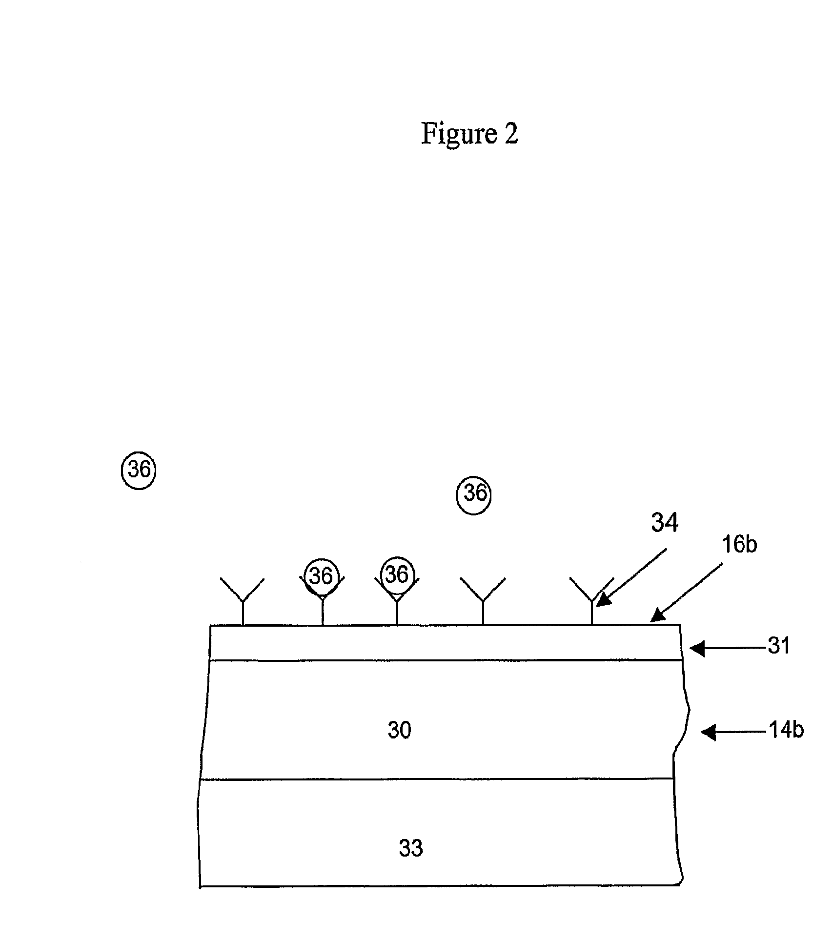
[0031]For the present inventions, phase modulation of a guided optical wave by application of an electric field to the hydrated surface of an optical waveguide with attached biomolecules has been demonstrated as well as by application of a magnetic field gradient to the surface of an optical waveguide with attached magnetic nanoparticles (MNPs).
E-Field Modulation of an Attached Biomolecule.
[0032]To demonstrate phase modulation of a guided optical wave by applying an electric field and moving attached biomolecules relative to the waveguide surface, an indium-tin oxide (ITO) waveguide was used. Thus the conductive ITO waveguide formed one electrode while a second electrode was formed through a metal film attached to the top of a thin cell used to confine aqueous solutions onto the waveguide surface. A bio film was produced by absorbing avidin to the waveguide surface. A sinusoidal AC (alternating current) source wa...
PUM
 Abstract
Description
Claims
Application Information