Exhaust Gas Purifying Catalyst and Production Method Thereof

Active Publication Date: 2009-04-30
NISSAN MOTOR CO LTD +1
View PDF5 Cites 16 Cited by
  • Summary
  • Abstract
  • Description
  • Claims
  • Application Information

AI Technical Summary

Benefits of technology

[0013]In accordance with the production method of an exhaust gas purifying catalyst according to the present

Problems solved by technology

However, in the case of using the impregnation method, the noble metal particles and such compound particles of the transition metal do not become the microparticles even if both thereof can be brought into contact with each other, or both cannot be brought into contact with each other or can be brought into little contact with each other even if both become the microparticles, and accordingly, it is difficult to arrange the compound particles of the transition metal in the vicinity of the noble metal particles as designed.
However, in the case of using the impre

Method used


Image

  • Exhaust Gas Purifying Catalyst and Production Method Thereof
  • Exhaust Gas Purifying Catalyst and Production Method Thereof
  • Exhaust Gas Purifying Catalyst and Production Method Thereof

Examples


example 1

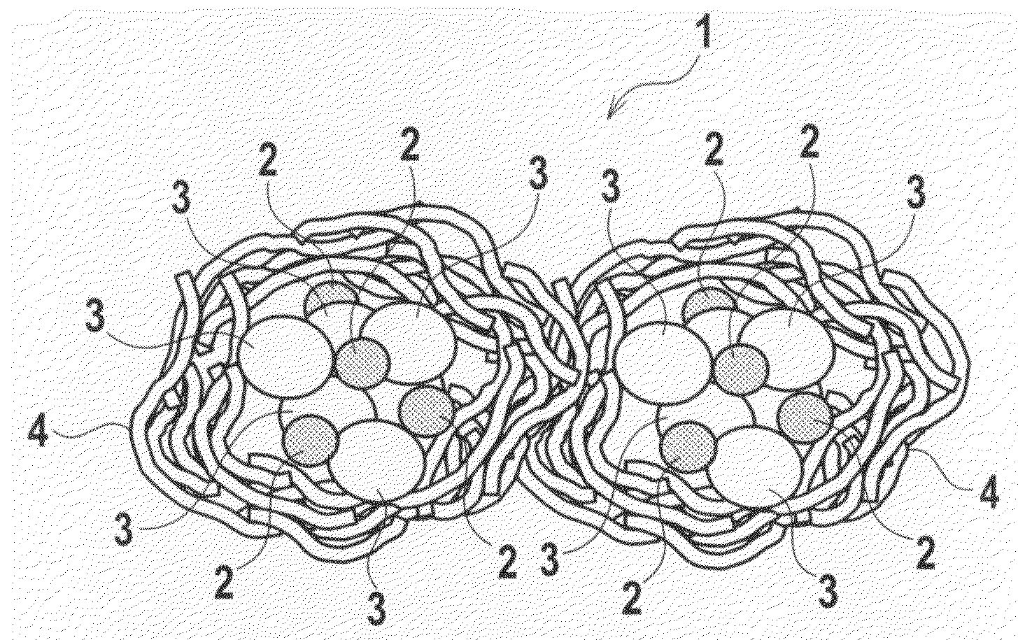
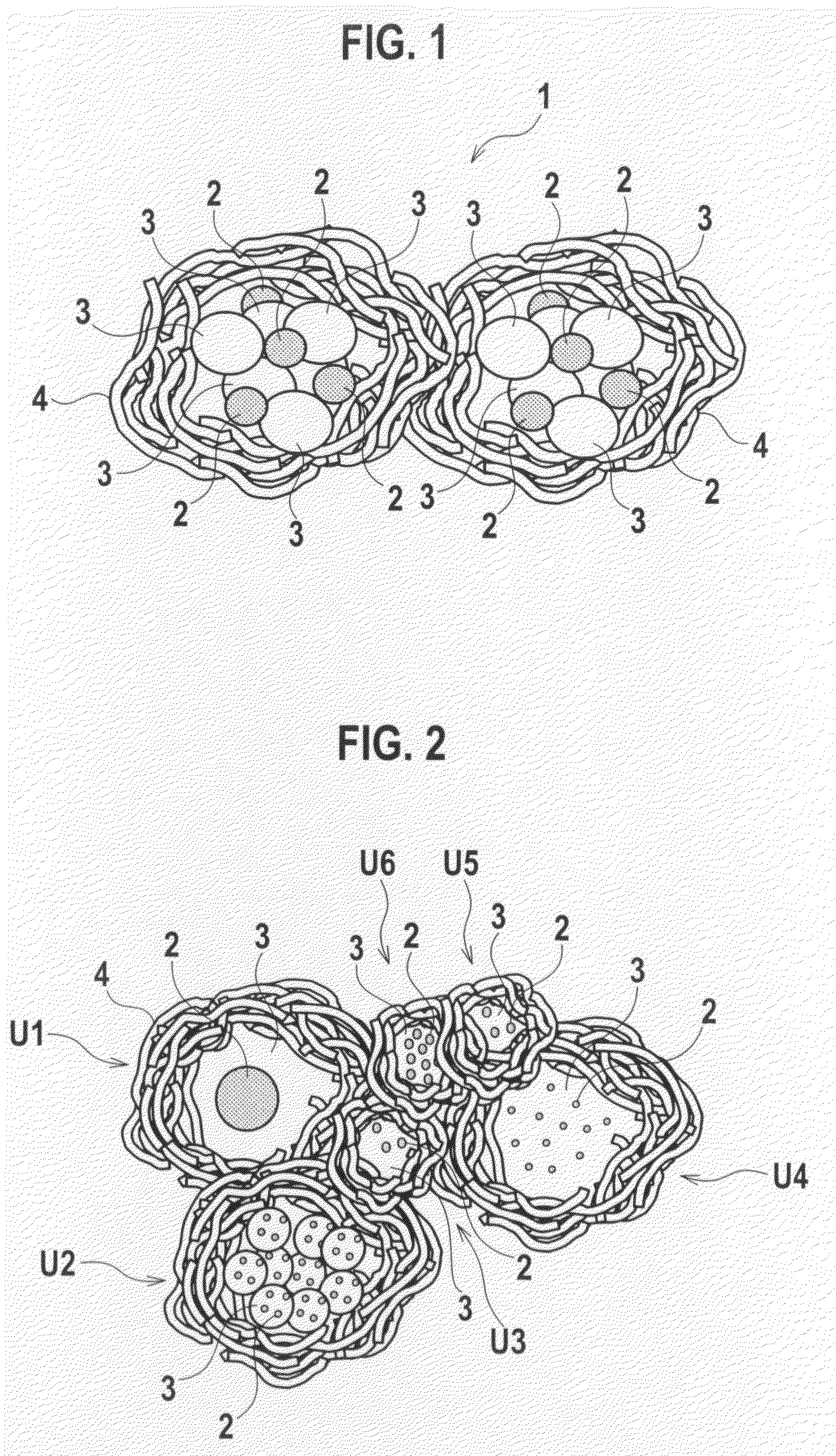
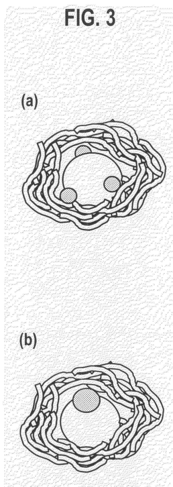
[0077]In Example 1, first, polyvinylpyrrolidone as surfactant was mixed into a mixed solution of water and ethanol, of which ratio was 1:1, so as to set a ratio of the surfactant with respect to such a solvent at 0.15 [mol / L ratio], followed by stirring, and thereafter, Ce acetate was added to an obtained solution, followed by stirring. Then, after the stirring was completed, ammonia was added to the solution, followed by another stirring for two hours, whereby a colloidal solution of Ce was prepared. Next, after dinitrodiamine Pt salt was added to the colloidal solution of Ce, ethanol was added thereto, and the solution was heated up to 80[° C.], whereby Pt salt was precipitated. Next, after aluminum isopropoxide was dissolved into a hexylene glycol solution, the Pt salt was poured into the solution. Then, after the solution was dried under reduced pressure in an evaporator, the solution was further dried in a dryer of 120[° C.], whereby catalyst powder was prepared. Then, finally,...

example 2

[0080]In Example 2, similar treatment to that of the above-described Example 1 was performed except that the ratio of the surfactant with respect to the solvent was set at 0.07 [mol / L ratio], whereby Pt, CeO2 / Al2O3 catalyst powder of Example 2 was prepared. Note that, in this catalyst powder, the average particle diameters of Pt and CeO2 were 2.4 and 28 [nm], respectively. Moreover, the contact ratio between Pt and CeO2 was 94[%].

example 3

[0081]In Example 3, similar treatment to that of the above-described Example 1 was performed except that the ratio of the surfactant with respect to the solvent was set at 0.35 [mol / L ratio], whereby Pt, CeO2 / Al2O3 catalyst powder of Example 3 was prepared. Note that, in this catalyst powder, the average particle diameters of Pt and CeO2 were 2.4 [nm] and 1 [nm], respectively. Moreover, the contact ratio between Pt and CeO2 was 96[%].


PUM

PropertyMeasurementUnit
Fractionaaaaaaaaaa
Substance countaaaaaaaaaa
Particle diameteraaaaaaaaaa

Abstract

An object is to maintain an effect of enhancing activity of noble metal particles by transition metal without increasing production cost and an environmental load.
An exhaust gas purifying catalyst 1 is composed of: noble metal particles 2; first compounds 3 which contact the noble metal particles 2 and suppress movement of the noble metal particles 2; and second compounds 4 which contain the noble metal particles 2 and the first compounds 3, suppress the movement of the noble metal particles 2, and suppress coagulation of the first compounds 3 following mutual contact of the first compounds 3, wherein the first compounds 3 support the noble metal particles 2, and simplexes or aggregates of the first compounds 3 supporting the noble metal particles 2 are included in section partitioned by the second compounds 4.

Description

TECHNICAL FIELD[0001]The present invention relates to an exhaust gas purifying catalyst suitable for application to treatment for purifying exhaust gas discharged from an internal combustion engine, and relates to a production method of the exhaust gas purifying catalyst.BACKGROUND ART[0002]In recent years, in order to remove harmful substances such as a hydrocarbon (HC) compound, carbon monoxide (CO) and carbon nitride (Nox), which are contained in exhaust gas exhausting from an internal combustion engine, an exhaust gas purifying catalyst in which particles of noble metal such as platinum (Pt) are supported on a support of a metal oxide such as alumina (Al2O3) has been being widely used. In the conventional exhaust gas purifying catalyst, a large amount of such noble metal particles are used in order to enhance durability of the noble metal particles against variations of an ambient atmosphere. However, it is not desirable to use the large amount of noble metal particles from a vi...

Claims


Application Information

Patent Timeline
IPC IPC(8): B01J23/10B01J23/38B01J23/74B01J23/34
CPCB01D53/945B01J23/38B01D2255/2073B01D2255/20738B01D2255/20753B01D2255/407B01D2255/9202B01J23/63B01J23/6562B01J23/894B01J35/0013B01J35/006B01J37/0215B01J37/0242B01J37/03B01J37/035Y02T10/22B01J2540/00B01J35/04B01D2255/102Y02T10/12B01D53/94B01J23/656B01J23/89
Inventor NAKAMURA, MASANORISUGA, KATSUOWAKAMATSU, HIRONORISHIRATORI, KAZUYUKIYASUDA, HIROFUMIAOYAMA, MAKOTOIKEZAWA, JUN
Owner NISSAN MOTOR CO LTD
Why Eureka
Try Eureka