
Multiplexing of optical beams using reversed laser scanning

a laser scanning and optical beam technology, applied in the field of optical multiplication, can solve the problems of inability to perfectly align original laser beams with each other, lack of bandwidth, and optical loss,

Inactive Publication Date: 2009-05-07
PRANALYTICA
View PDF18 Cites 35 Cited by
  • Summary
  • Abstract
  • Description
  • Claims
  • Application Information

AI Technical Summary

Benefits of technology

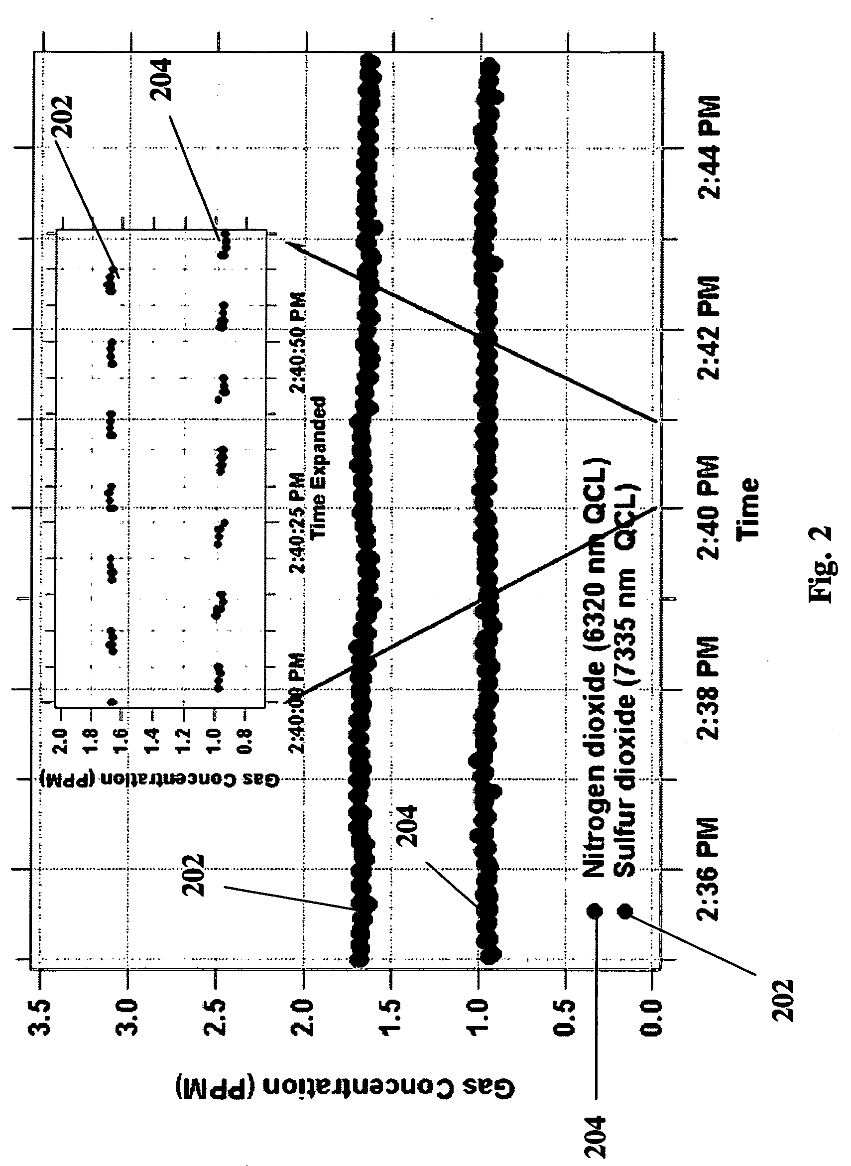
[0042]Additionally, the multiplexed optical beam system set forth herein may be used to help detect mixtures of optically active compounds that are responsive to the selected or available laser wavelengths.
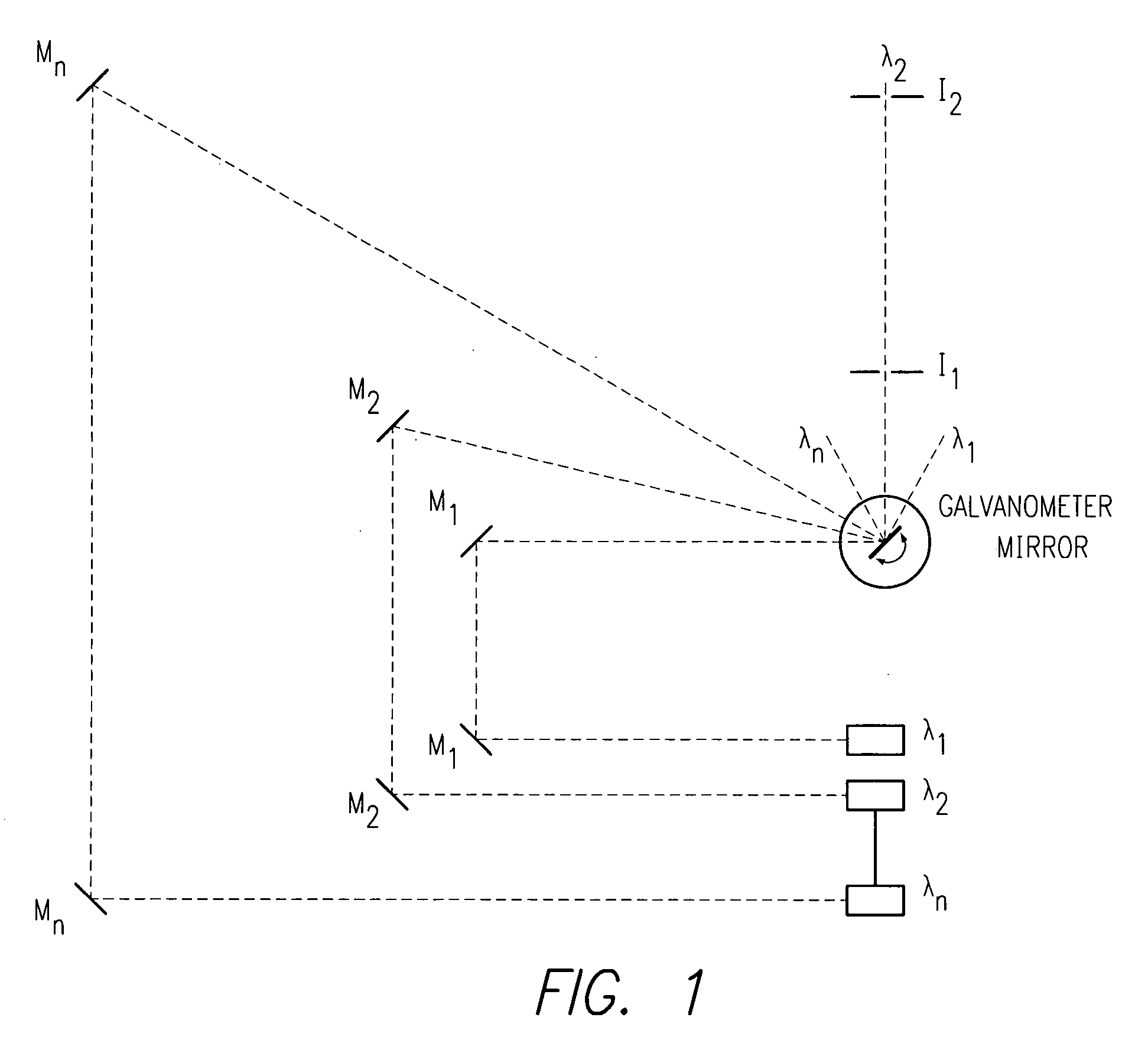
[0043]The present invention may be used in a variety of applications and may serve to enable and provide operability in many technological areas including: providing and enabling a reverse laser scanning technique for combining a plurality of laser beams into one beam; providing and enabling a galvanometer mirror to be used as the combiner for the plurality of the beams; providing and enabling two (2) independent beam alignment elements per laser beam to combine the plurality of lasers to go through one defined laser beam path; providing and enabling multi-chemical detection using multiple lasers in the same device and in remote sensing; providing and enabling remotely operated laser switching for medical surgery and diagnosis; providing and enabling wavelength, code and time division multiplexing in communication systems; and providing and enabling the routing of optical beams.
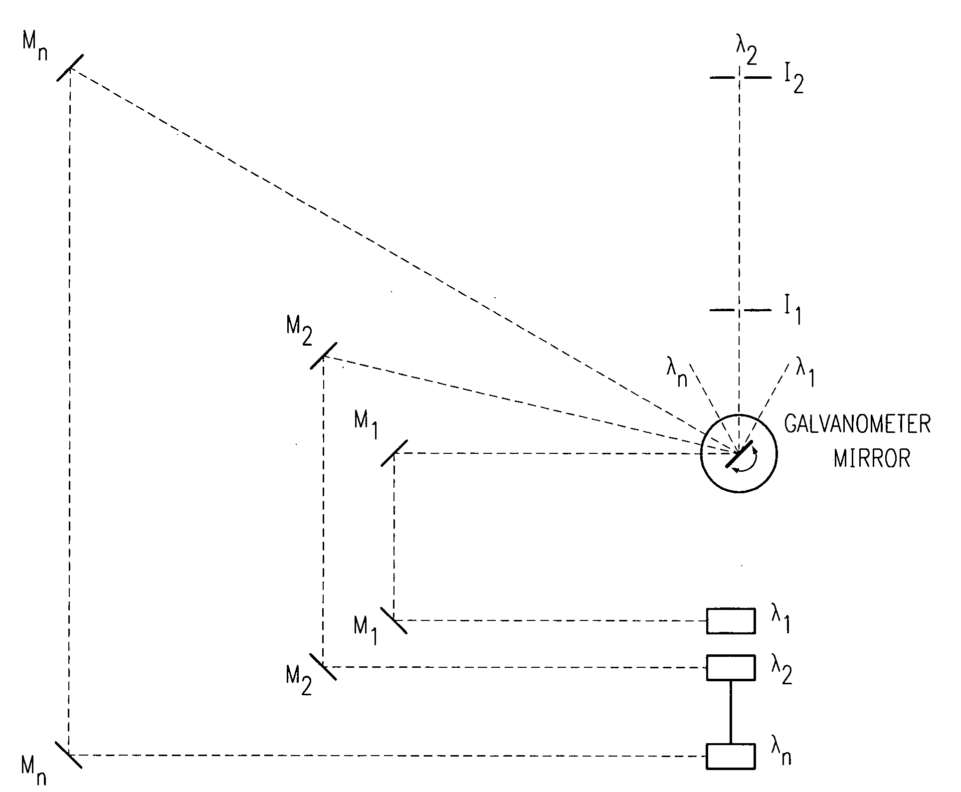
[0044]In one embodiment of the present invention, a laser system for providing laser light at a plurality of selectable wavelengths includes a first source of first laser light having a first wavelength and a second source of second laser light having a second wavelength. A mirror controllably pivots on an axis with the first and second laser light incident upon the mirror on the axis at respective and different first and second coplanar angles. A collimator is provided that segregatably selects a beam of light. The mirror is selectably adjustable to reflect one of the first and second laser light through the collimator such that the laser system can selectably transmit either the first laser light or the second laser light according to selectable adjustment of the mirror.

Problems solved by technology

In-plane integrated optical multiplexing schemes used in communications industry are not appropriate for the above needs1-6 because the long wavelength radiation needed for these applications cannot be handled using the optical materials used for the fabrication of such planar multiplexing schemes.
Optical multiplexing using dispersive optical elements such as gratings, bandpass filters, prisms etc., currently lacks bandwidth and entails optical losses.
In the merged laser beam, however, the original laser beams cannot easily be perfectly aligned with each other.
The Aagano et al. system depends on polarization of the individual beams and may put limits on the number of beams that could be used.
This is not possible unless the mirror is equipped with a fast angular positioning like a galvanometer and at least there are two independent beam positioning mirrors per laser beam.
Broad band filters with high throughput cannot be used for combing beams of closely spaced wavelengths.
The Sakata et al. system does not allow nearly 100% throughput with no restriction on wavelength separation of individual beams.

Method used


Image

  • Multiplexing of optical beams using reversed laser scanning
  • Multiplexing of optical beams using reversed laser scanning
  • Multiplexing of optical beams using reversed laser scanning

Examples


Embodiment Construction

)

[0053]The detailed description set forth below in connection with the appended drawings is intended as a description of presently-preferred embodiments of the invention and is not intended to represent the only forms in which the present invention may be constructed and / or utilized. The description sets forth the functions and the sequence of steps for constructing and operating the invention in connection with the illustrated embodiments. However, it is to be understood that the same or equivalent functions and sequences may be accomplished by different embodiments that are also intended to be encompassed within the spirit and scope of the invention.

[0054]The masculine pronoun is generally used herein to indicate the generic individual and as a matter of convention and convenience.

[0055]Referring to the drawings, where like numerals of reference designate like elements throughout, it will be noted that the present invention resides in a system for providing laser beams of selectab...


PUM


Abstract

A high efficiency, low cost, nondispersive optical multiplexing arrangement for optical beams, used a technique denominated “Reverse Laser Scanning.” In the Reverse Laser Scanning operation, different laser beams angularly meet on the rotational axis of a galvanometer-mounted mirror or the like. Upon reflection from the mirror, each of the laser beams is propagated along one defined direction by appropriate angular positioning of the galvanometer mirror. The process enables several useful deployments, including multi-chemical detection using several lasers in the same sensor, remotely operated laser switching for medical surgery and diagnosis where multiple lasers may be used, and wavelength, code, and time division multiplexing in communication systems, among others.

Description

COPYRIGHT AUTHORIZATION[0001]Portions of the disclosure of this patent document may contain material which is subject to copyright and / or mask work protection. The copyright and / or mask work owner has no objection to the facsimile reproduction by anyone of the patent document or the patent disclosure, as it appears in the Patent and Trademark Office patent file or records, but otherwise reserves all copyright and / or mask work rights whatsoever. 37 C.F.R. § 1.71(d).BACKGROUND OF THE INVENTION[0002]1. Field of the Invention[0003]This invention relates to the multiplexing of optical, and preferably laser, beams.[0004]2. Description of the Related Art[0005]There is a growing need for and many advantages can be obtained by an efficient, high bandwidth, high optical power handling capacity, and cost effective laser and / or optical multiplexing device and method that can be used in several fields including chemical sensing, medical surgery, semiconductor manufacture, and metrology applicati...

Claims


Application Information

Patent Timeline
Patent Type & Authority Applications(United States)
IPC IPC(8): H01S3/10H01S3/08
CPCA61B5/0059H01S3/23H04J14/02H04B10/506H04J14/005H01S5/4087
Inventor PATEL, C.KUMAR N.MUKHERJEE, ANADIPRASANNA, MANU
Owner PRANALYTICA
Learn More