Exhaust gas purifying apparatus for internal combustion engine

a technology for exhaust gas purification and internal combustion engines, which is applied in mechanical equipment, engine components, machines/engines, etc., can solve the problems of deterioration of added quantity, erroneous computation of nox purifying ratio, and inability to accurately compute nox purifying ratio

Inactive Publication Date: 2009-05-14
DENSO CORP +1
View PDF1 Cites 17 Cited by
  • Summary
  • Abstract
  • Description
  • Claims
  • Application Information

AI Technical Summary

Benefits of technology

[0007]The present invention is made in view of the above matters, and it is an object of the present invention to provide an exhaust gas purifying apparatus for an int

Problems solved by technology

In such a case, there is a possibility that the NOx purifying ratio is erroneously computed based on the NOx sensor output.
If the accuracy of the NOx purifying ratio is deteriorated, the accurac

Method used


Image

  • Exhaust gas purifying apparatus for internal combustion engine
  • Exhaust gas purifying apparatus for internal combustion engine
  • Exhaust gas purifying apparatus for internal combustion engine

Examples


Embodiment Construction

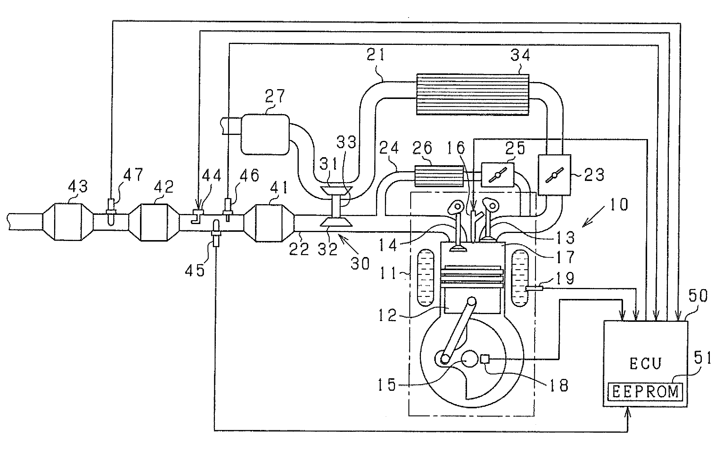
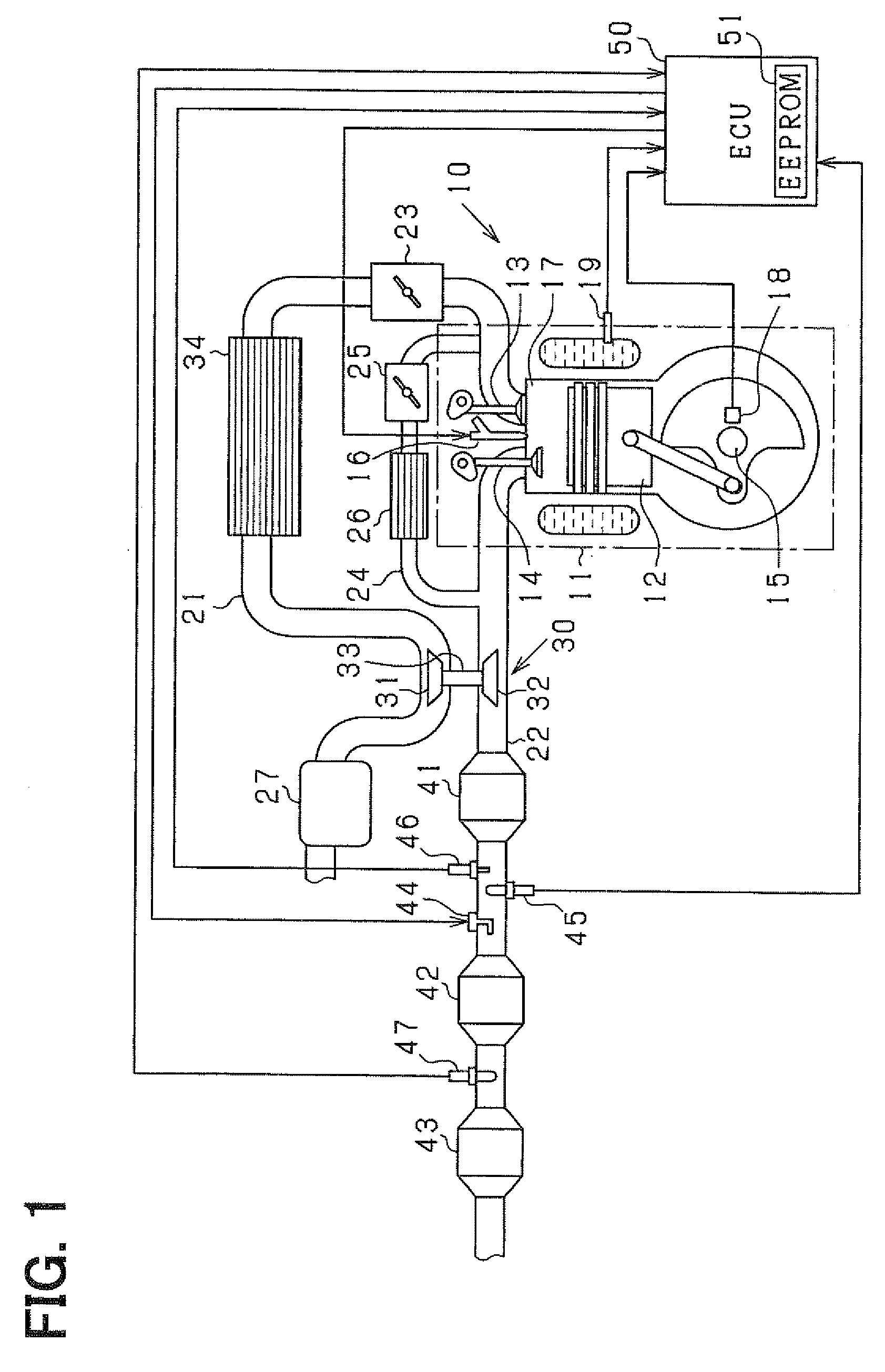
[0037]Hereafter, an embodiment of the present invention is described. In this embodiment, a multi-cylinder diesel engine is controlled. An electronic control unit (ECU) performs a various kind of controls to the engine. The diesel engine has a common-rail fuel injection system and a urea SCR system, Referring to FIG. 1, the system is schematically explained, hereinafter.

[0038]The engine 10 includes an engine body 11 which has a piston 12, an intake valve 13, and an exhaust valve 14. A reciprocative movement of the piston 12 rotates a crankshaft 15. A fuel injector 16 is provided on a cylinder head with respect to each cylinder. The fuel injector 16 injects fuel into a combustion chamber 17 directly, which is combusted in the combustion chamber 17.

[0039]The crankshaft 15 is provided with a crank angle sensor 18 which detects a rotation of the crankshaft 15. A cylinder block is provided with a coolant temperature sensor 19 which detects coolant temperature.

[0040]A fuel supply system w...


PUM


Abstract

An exhaust pipe is provided with an oxidation catalyst, a SCR catalyst (ammonia selective reduction catalyst), and an ammonia slip catalyst. In the exhaust pipe, the urea water adding valve is provided between the oxidation catalyst and the SCR catalyst. A NOx sensor which detects the NOx quantity in an exhaust gas is provided downstream of the SCR catalyst. An ECU controls the urea water adding valve to add the urea water to the exhaust gas. While the urea water is added to the exhaust gas, the ECU successively obtains a NOx sensor output, and computes an adding quantity command value in which the NOx sensor output becomes minimum.

Description

CROSS-REFERENCE TO RELATED APPLICATION[0001]This application is based on Japanese Patent Application No. 2007-290828 filed on Nov. 8, 2007, the disclosure of which is incorporated herein by reference.FIELD OF THE INVENTION[0002]The present invention relates to an exhaust gas purifying apparatus for an internal combustion engine, which is preferably applied to an exhaust gas purifying system of Selective Catalytic Reduction (SCR) type using ammonia reducing agent such as urea aqueous solution (urea water).BACKGROUND OF THE INVENTION[0003]A urea Selective Catalytic Reduction (SCR) system has been developed as an exhaust gas purifying apparatus which purifies nitrogen oxide (NOx) in an exhaust gas exhausted from an internal combustion engine, especially from a diesel engine. The urea SCR system has following configuration:[0004]That is, in the urea SCR system, a selective catalytic reduction type NOx reduction catalyst (SCR catalyst) is provided in an exhaust gas pipe connected to an e...

Claims


Application Information

Patent Timeline
IPC IPC(8): F01N3/20
CPCF01N3/0814F01N3/208F01N2560/026F01N2570/18Y02T10/24F01N2610/146F01N2900/0408F01N2900/14F02B37/00F01N2610/02Y02T10/12
Inventor FUJITA, TATSUYAMARUYAMA, MASATOSHI
Owner DENSO CORP
Why Eureka
Try Eureka