Method for Maximum Efficiency of Non-Condensing Boiler

a non-condensing boiler and maximum efficiency technology, applied in the direction of heating types, electric controllers, instruments, etc., can solve the problems of inability to inhibit the corrosion of the boiler, incur expensive production costs, and cause corrosion, etc., to achieve easy assembly, prolong the durability, and reduce production costs. cost

Inactive Publication Date: 2009-05-14
KYUNGDONG NAVIEN
View PDF6 Cites 7 Cited by
  • Summary
  • Abstract
  • Description
  • Claims
  • Application Information

AI Technical Summary

Benefits of technology

[0013]With this configuration, no condensation takes place during operation of the non-condensing boiler, so that the boiler can extend its durability, be easily assembled with inexpensive production costs, be made compact, and obtain maximum heat efficiency under a non-condensation condition.

Problems solved by technology

In the condensing heat exchanger, however, corrosion takes place due to acidic liquid of about pH 2 to 4 which is produced by the reaction of moisture produced during condensation with sulfur oxides (in the case of the oil) or nitrogen oxides (in the case of the gas) in the exhaust gas, as well as combustion heat.
Inhibition of this corrosion has always emerged as a problem.
However, these condensing heat exchangers are difficult to manufacture, and are large in size and heavy in weight, so that they incur expensive production costs.
Consequently, these factors act as considerable restrictions in realizing the simple assembly of the heat exchangers.
When condensed water is brought into contact with the heat exchanger made of this material, serious corrosion takes place, which decreases heat exchange efficiency, and causes the function of the heat exchanger to be lost in the long run.

Method used


Image

  • Method for Maximum Efficiency of Non-Condensing Boiler
  • Method for Maximum Efficiency of Non-Condensing Boiler

Examples


Embodiment Construction

[0016]Hereinafter, exemplary embodiments of the present invention will be described in detail with reference to the attached drawings.

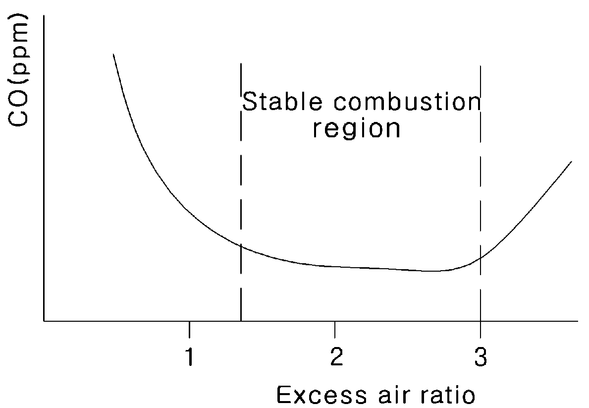
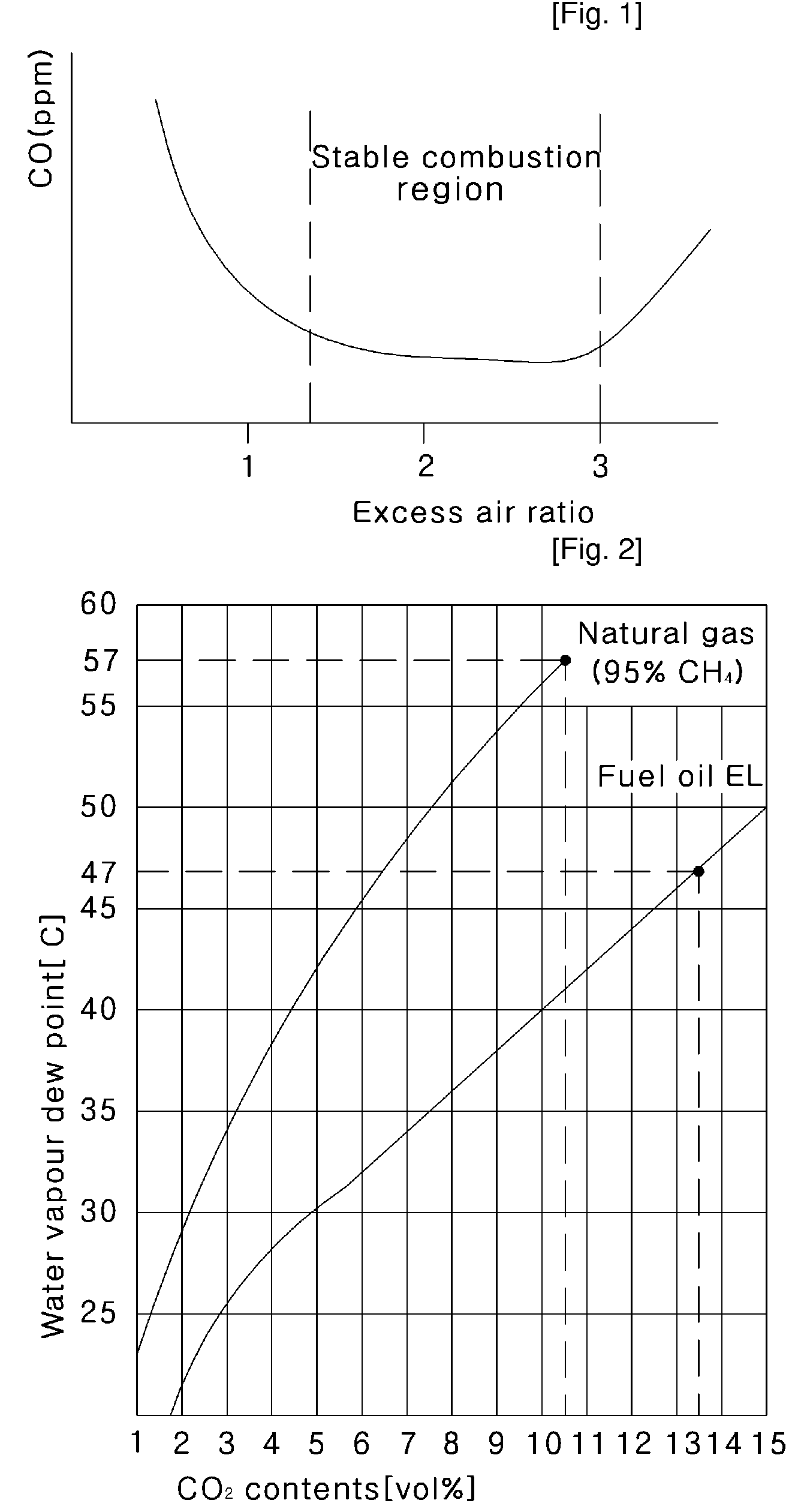
[0017]In the brief description of the attached drawings, FIG. 1 shows a combustion characteristic curve (graphic relationship between an excess air ratio and carbon monoxide (CO)) in accordance with an exemplary embodiment of the present invention, and FIG. 2 is a graph plotting the relationship between the concentration of CO2 and a dew point temperature in accordance with an exemplary embodiment of the present invention.

[0018]FIG. 1 shows the range of an excess air ratio required for stable combustion of a burner (i.e. combustion when the amount of CO produced by unstable combustion is minimal).

[0019]Referring to FIG. 2, it is assumed that an oil fuel is used. When CO2 amounts to 10.5 vol %, condensed water is formed at about 43° C. When the excess amount of air is reduced, and CO2 in an exhaust gas amounts to 13.5 vol %, the condensed water is form...


PUM


Abstract

Provided is a method for operating a non-condensing boiler at maximum non-condensation efficiency, and more particularly a method for operating a non-condensing boiler, capable of supplying an appropriate amount of excess air for combustion of a burner, avoiding damaging a heat exchanger due to the condensed water generated at the heat exchanger, and effectively improving the heat efficiency. The method comprises the steps of: sensing a temperature of exchange water introduced into a heat exchanger and a temperature of supply water discharged from the heat exchanger and calculating an average temperature from the two temperatures to obtain a maximum concentration of CO using information stored in a controller; calculating a ratio of excess air (λ) from the maximum concentration of CO using a combustion equation chosen depending on a fuel used; checking from a combustion characteristic curve whether or not the excess air ratio (λ) is within a stable combustion region; when the excess air ratio (λ) is within the stable combustion region, setting this excess air ratio to the control target value, and when the excess air ratio (λ) is less than a lower limit of the stable combustion region, setting a minimum excess air ratio of the stable combustion region to the control target value; calculating a target value of air flow suitable for the current consumption amount of fuel based on the set excess air ratio; and performing feedback control with respect to the air flow target value and a value input from an air flow sensor. With this configuration, no condensation takes place during operation of the non-condensing boiler, so that the boiler can have increased durability, be easily assembled at inexpensive production costs, be made compact, and obtain maximum heat efficiency under a non-condensation condition.

Description

TECHNICAL FIELD[0001]The present invention relates to a method for operating a non-condensing boiler at maximum non-condensation efficiency, and more particularly to a method for operating a non-condensing boiler, in which an appropriate amount of excess air is supplied for stable combustion of a burner, and water vapor formed by combustion of fuel is prevented from condensing on a heat exchanger of the boiler and damaging the heat exchanger, thereby effectively increasing heat efficiency.BACKGROUND ART[0002]Boilers that are mainly used in ordinary homes to heat and supply hot water are categorized into gas boilers and oil boilers according to the type of fuel used. The gas boilers sometimes use liquefied petroleum gas (LPG) as fuel, but mostly use liquefied natural gas (LNG), which is a clean fuel capable of minimizing air pollution because it contains almost none of a sulfur (S) component, compared to light oil or kerosene used for the oil boilers.[0003]The boilers can be classifi...

Claims


Application Information

Patent Timeline
Patent Type & Authority Applications(United States)
IPC IPC(8): F24H9/20
CPCF23N1/10F23N5/006F24H9/0036F23N2025/20F23N2025/30F23N2025/19F23N2225/19F23N2225/20F23N2225/30F23N5/003F23N2900/05002F24D19/1009F24D2220/042F24H9/2035F23N2225/18Y02B30/00
Inventor MIN, TAE-SIK
Owner KYUNGDONG NAVIEN
Why Eureka
Try Eureka