Electrical impedance tomography of nanoengineered thin films

Active Publication Date: 2009-05-14
RGT UNIV OF MICHIGAN
View PDF5 Cites 56 Cited by
  • Summary
  • Abstract
  • Description
  • Claims
  • Application Information

AI Technical Summary

Benefits of technology

[0011]As opposed to relying on global-based SHM methods, guided-waves show tremendous promise for damage detection and localization in thin metallic structures. With ultrasonic waves able to propagate over long distances, this sensing approach provides the sensor with a large interrogation zone. For instance, Giurgiutiu, et al. bonds multiple arrays of surface-mounted piezoelectric transducers onto aluminum alloy aircraft panels for generating Lamb waves to detect cracks and corrosion damage. Using piezoelectric sensor/actuator responses, reflected echo signals are employed for accurate detection of damage due to hairline slits, seeded cracks, and impact. Similarly, Park, et al. has validated piezoelectric patches for identifying cracks developed in welded zones of ⅛-scale bridge truss members. Simulated damage by loose bolts and induced cracks are successfully detected via a Lamb-wave approach combined with a prescribed damage threshold index. On the other hand, when combining distributed piezoelectric sensors/actuators with a wavelet-based data processing technique, Sohn, et al. identifies the location of delamination within large 61×61 cm2 composite plates. While the aforementioned guided wave techniques are fairly robust for identifying damage in simple structural components, computational demand increases dramatically and accuracy decreases when structural geometries are complex and when multiple damage sites are wit

Problems solved by technology

If the sample resistance, R, is low, contact impedance of the probes can introduce measurement errors.
An inherent limitation of both DC probe and EIS methods is the assumption of relative homogeneity of the specimen's electrical properties between probe points.
While such methods provide a mapping of resistance over multiple dimensions, they require repeated time-consuming measurements that are conducted at the macro- or microscales.
In addition, harsh operational and environmental conditions coupled with the lack of robust monitoring and maintenance schemes often accelerate structural degradation.
In extreme cases, undetected structural damage such as impact damage, corrosion, and fatigue can lead to catastrophic system failure.
For instance, undiagnosed corrosion of aircraft fuselages can result in over-stressing of rivets and stress-corrosion crack formation; an example of what can occur if damage is left undetected is the Aloha Airlines plane which ripped apart in-flight in 1988.
M

Method used


Image

  • Electrical impedance tomography of nanoengineered thin films
  • Electrical impedance tomography of nanoengineered thin films
  • Electrical impedance tomography of nanoengineered thin films

Examples


Embodiment Construction

1. General Matters

[0056]Example embodiments will now be described more fully with reference to the accompanying drawings. Numerous specific details are set forth such as examples of specific components, devices, and methods, to provide a thorough understanding of embodiments of the present disclosure. It will be apparent to those skilled in the art that specific details need not be employed, that example embodiments may be embodied in many different forms and that neither should be construed to limit the scope of the disclosure. In some example embodiments, well-known processes, well-known device structures, and well-known technologies are not described in detail.

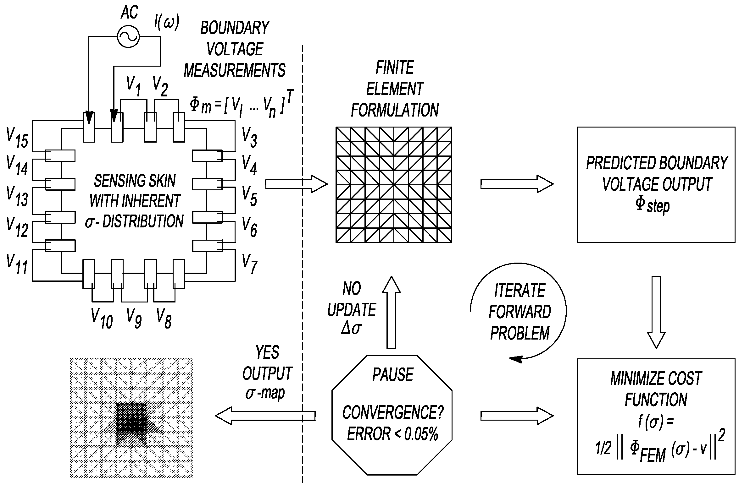
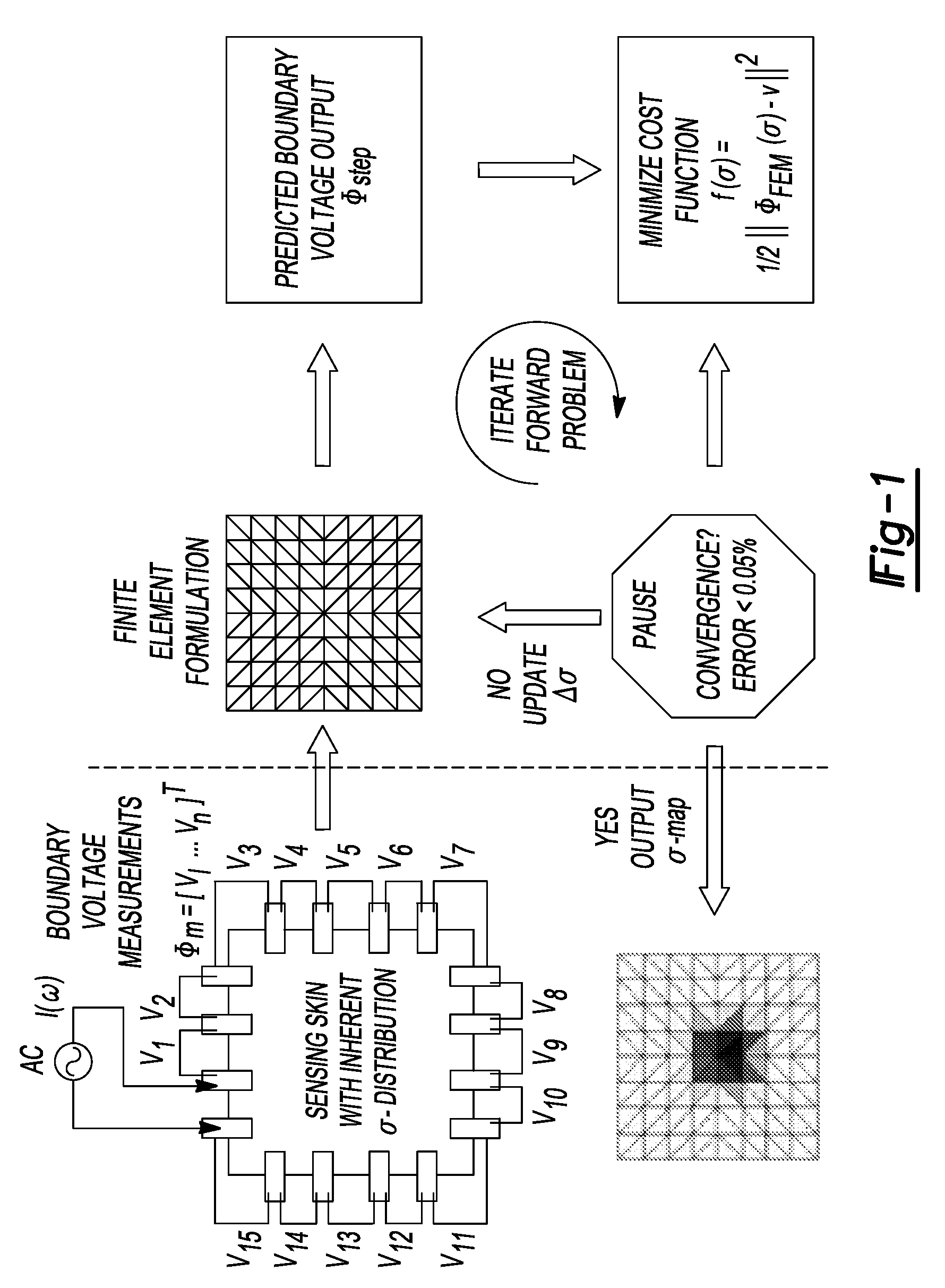
2. Electrical Impedance Tomography

2.1 Forward Problem: Background and Theoretical Foundations

[0057]Given any two- (2D) or three-dimensional (3D) linear isotropic medium (Q) described by a time-invariant conductivity distribution (σ), Faraday's Law of Induction states,

∇×E-∂∂tB(1)

and Ampere's Law states:

∇×H=σE+Js  (2)

where E ...


PUM


Abstract

The present teachings relate to the application of electrical impedance tomography (EIT) to demonstrate the multifunctionality of carbon nanocomposite thin films under various types of environmental stimuli. Carbon nanotube (CNT) thin films are fabricated by a layer-by-layer (LbL) technique or other techniques and mounted with electrodes along their boundaries. The response of the thin films to various stimuli determined by relying on electric current excitation and corresponding boundary potential measurements. The spatial conductivity variations are reconstructed based on a mathematical model for the EIT technique. Here, the ability of the EIT method to provide two-dimensional mapping of the conductivity of CNT thin films is validated by (1) electrically imaging intentional structural defects in the thin films and (2) mapping the film's response to various pH environments.

Description

CROSS-REFERENCE TO RELATED APPLICATIONS[0001]This application claims the benefit of U.S. Provisional Application No. 60 / 994,031, filed on Sep. 14, 2007. The entire disclosure of the above application is incorporated herein by reference.GOVERNMENT SUPPORT[0002]This invention was made with government support under Grant Number CMS0528867 awarded by the National Science Foundation. The government has certain rights in the invention.BACKGROUND AND SUMMARY[0003]This section provides background information related to the present disclosure which is not necessarily prior art. This section further provides a general summary of the disclosure, and is not a comprehensive disclosure of its full scope or all of its features.[0004]The emerging field of nanotechnology puts forth nanomaterials with desired mechanical, electrical, and chemical functionality at the macroscopic scale. Advances in the field have aided the development of multifunctional materials that are capable of achieving several f...

Claims


Application Information

Patent Timeline
IPC IPC(8): G01N27/02
CPCG01R27/02
Inventor LYNCH, JEROME P.HUO, TSUNG-CHINKOTOV, NICHOLAS A.KAM, NADINE WONG SHILOH, KENNETH J.
Owner RGT UNIV OF MICHIGAN
Why Eureka
Try Eureka