
Source-Measure Unit Based on Digital Control Loop

a digital control loop and source-measure technology, applied in the field of measurement and data acquisition system design, can solve the problems of increasing the the decrease of achieve the effect of reducing the accuracy requirements of the dac, eliminating noise, and adding flexibility of the smu

Active Publication Date: 2009-05-14
NATIONAL INSTRUMENTS
View PDF5 Cites 81 Cited by
  • Summary
  • Abstract
  • Description
  • Claims
  • Application Information

AI Technical Summary

Benefits of technology

The patent describes an SMU (source-measure unit) that can measure and regulate the output of current and voltage. The SMU uses a digital control loop, which allows for more flexibility and accuracy in measuring and controlling the output. The SMU can measure the voltage across the terminals of a device under test or the current flowing into the device. The readback values are obtained by averaging the current and voltage values to provide noise rejection advantages. The digital control loop can correct errors in the output and offer the potential for novel approaches to solving range-switching issues. Overall, the patent describes a more efficient and accurate way to measure and control the output of current and voltage.

Problems solved by technology

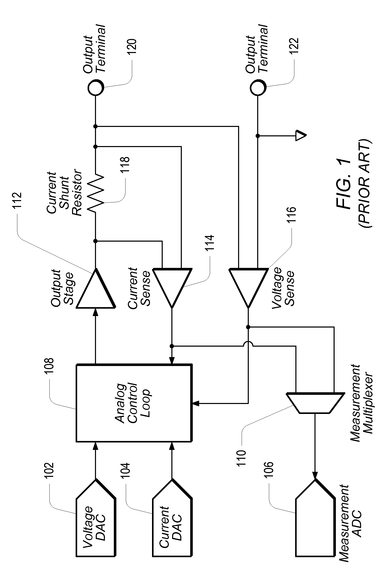
Placing the control loop in the digital domain may result in added flexibility of the SMU, and a decrease in the accuracy requirements on the DAC.

Method used


Image

  • Source-Measure Unit Based on Digital Control Loop
  • Source-Measure Unit Based on Digital Control Loop
  • Source-Measure Unit Based on Digital Control Loop

Examples


second embodiment

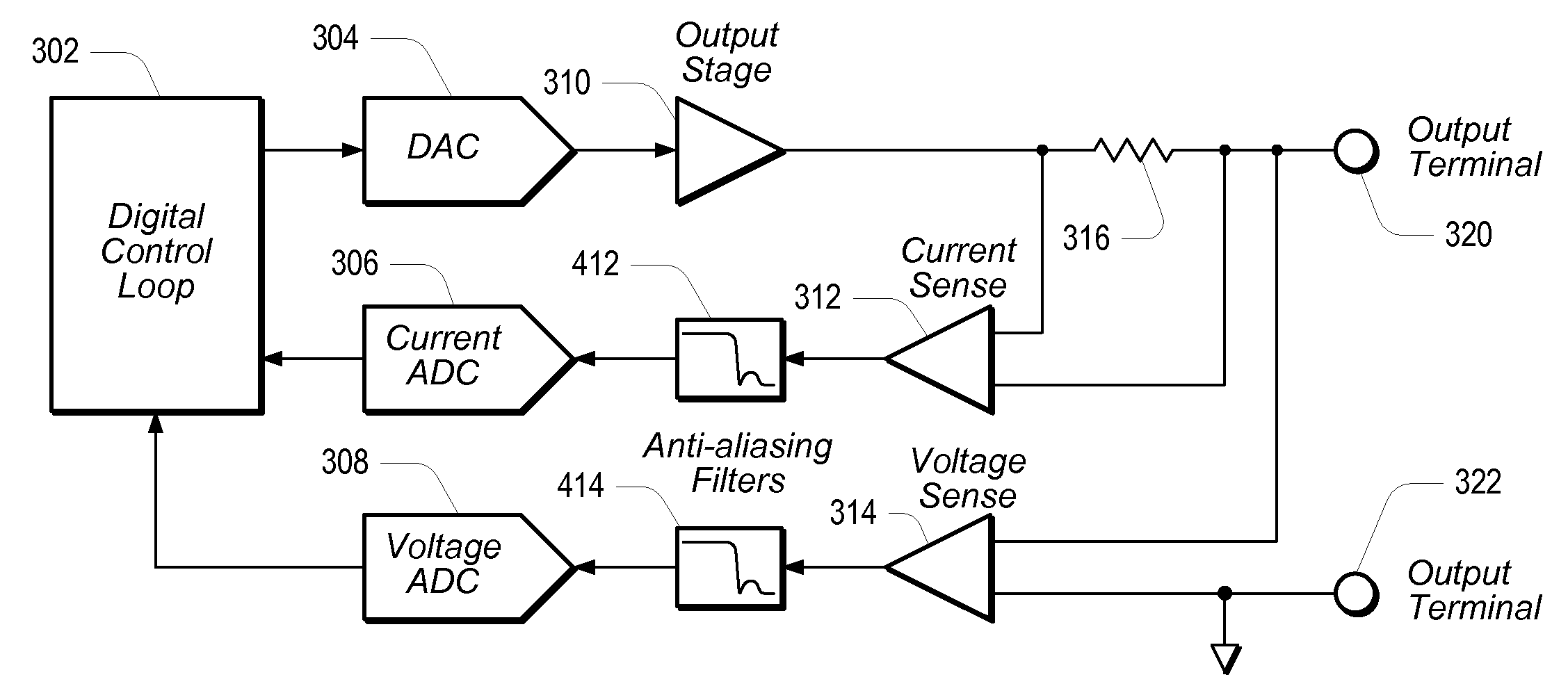
[0037]FIG. 4 shows a novel SMU in which anti-alias filtering has been added to the ADCs. As shown in FIG. 4, anti-alias filter 412 may be coupled between Current Sense element 312 and Current ADC 306, and anti-alias filter 414 may be coupled between Voltage Sense element 314 and Voltage ADC 308. Anti-alias filters 412 and 414 may operate to ensure that DCL 320 does not respond to out-of-band disturbances.

third embodiment

[0038]FIG. 5 shows a novel SMU in which shunt switching has been added in the feedback loop between the output (output terminal 320) and Current ADC 306. As shown in FIG. 5, different current shunt resistors 516 may be switched into the feedback loop between the output of Output Stage 310 and the inputs of Current Sense element 312, using a multiplexer 524 and a set of switches 518. While FIG. 5 shows three switches (518) and three current shunt resistors (516), alternate embodiments may be configured with a greater or lesser number of switches and / or resistors, as desired. Shunt switching may provide the SMU with the capability to cover a wider dynamic range of current. Any glitches that may result from switching between the various current shunt resistors may be minimized by adjusting the settings of DAC 304 simultaneously with the shunt-switching operation. Since the current is being measured and the values of the current shunt resistors (516) are known, it is possible to calcula...

fourth embodiment

[0039]FIG. 6 shows a novel SMU configured to further minimize glitches that may occur when switching between current shunt resistors 516 that have been added in the feedback loop between the output and Current ADC 306. In this case, if switches 518 happen to be slow switches, they may be operated gradually to transition between the shunt resistors (516). Current shunt resistors 516 may also be switched into the feedback loop between the output of Output Stage 310 and the inputs of a second Current Sense element 612, using additional multiplexer 624, with the output of additional Current ADC 606 be coupled back to DCL 302. Additional Current ADC 606 and additional Current Sense element 612 may be provided to make it possible to simultaneously measure the current conducted by two different current shunt resistors. Thus a reading of the total current may be obtained during the shunt-switching operation, while DCL 302 remains stable and predictable. One possible way to reduce the number...


PUM


Abstract

A source-measure unit (SMU) may be implemented with a control loop configured in the digital domain. The output voltage and output current may be measured with dedicated ADCs (analog-to-digital converters). The readings obtained by the ADCs may be compared to a setpoint, which may be set in an FPGA (field programmable gate array) or DSP (digital signal processing) chip. The FPGA or DSP chip may then be used to produce an output to drive a DAC (digital-to-analog converter) until the output voltage and / or output current reach the respective desired levels. The readback values may be obtained by averaging the voltage and / or current readings provided by the ADCs. The averaging may be weighted to improve noise rejection. The digital control loop provides added flexibility to the SMU and a decrease in the accuracy requirements on the DAC, while also for solving potential range-switching issues that may arise within the SMU.

Description

PRIORITY CLAIM [0001]This application claims benefit of priority of Provisional Application Ser. No. 60 / 986,380 titled “Source-Measure Unit Based on Digital Control Loop” and filed on Nov. 8, 2007, whose inventor is Chris Regier, which is hereby incorporated by reference in its entirety as though fully and completely set forth herein.BACKGROUND OF THE INVENTION [0002]1. Field of the Invention[0003]This invention relates generally to measurement and data acquisition systems and, more particularly, to the design of source-measure units.[0004]2. Description of the Related Art[0005]Scientists and engineers often use measurement systems to perform a variety of functions, including measurement of a physical phenomena a unit under test (UUT) or device under test (DUT), test and analysis of physical phenomena, process monitoring and control, control of mechanical or electrical machinery, data logging, laboratory research, and analytical chemistry, to name a few examples.[0006]A typical meas...

Claims


Application Information

Patent Timeline
Patent Type & Authority Applications(United States)
IPC IPC(8): H03M1/66H03M1/12
CPCG01R31/2841G01R31/31924G01R31/3163
Inventor REGIER, CHRISTOPHER G.
Owner NATIONAL INSTRUMENTS
Learn More