Melt-kneaded products, molded resin products, and production method thereof

a technology of molded resin and elastomer, which is applied in the direction of mixing/kneading with horizontally mounted tools, applications, transportation and packaging, etc. it can solve the problems of not being able to achieve such uniform dispersion, not being able to provide satisfactory, and not being able to meet the requirements of uniform dispersion, etc., to achieve excellent elastomer properties, improve mechanical performance properties, and improve the effect of elasticity and elong

Inactive Publication Date: 2009-05-14
NAT INST OF ADVANCED IND SCI & TECH
View PDF4 Cites 28 Cited by
  • Summary
  • Abstract
  • Description
  • Claims
  • Application Information

AI Technical Summary

Benefits of technology

[0058]According to at least an embodiment of the present invention, a melt-kneading method to uniformly disperse a filling material constituted by a filler in a rubber, elastomer, thermoplastic resin or thermosetting resin is provided and that, by using this melt-kneading method a melt-kneaded product in which a filling material constituted by a filler is uniformly dispersed in a rubber, elastomer, thermoplastic resin or thermosetting resin can be obtained.
[0059]In addition, by subsequently molding the product obtained by the melt-kneading method using T-dies or various other dies, a molded product in which a filling material constituted by a filler is uniformly dispersed in a rubber, elastomer, thermoplastic resin or thermosetting resin can be obtained.
[0060]If a rubber or elastomer is used, the obtained product exhibits excellent elastomer properties such as flexibility, rubber elasticity and shape recoverability after deformation, while the characteristics of the filler constituting the filling material can also be exhibited fully to dramatically improve the mechanical performance properties such as high modulus of elasticity and elongation at break, and also improve the electrical conductivity, so that the obtained elastomer product can be used widely in various parts and members including films, sheets and tubes, in the forms of flexible hoses, rings and sealants, for example.
[0061]Also, a thermoplastic resin or thermosetting resin can be used to create a material offering excellent characteristics, by fully demonstrating the characteristics of the filler constituting the filling material, for use in automotive parts and in various other fields including electrical and electronics. The achieved material is also useful as a vibration-absorbing material or anti-vibration material offering favorable electrical characteristics such as dramatically improved modulus of elasticity and other mechanical performance characteristics as well as electrical conductivity.
[0062]For purposes of summarizing the invention and the advantages achieved over the related art, certain objects and advantages of the invention are described in this disclosure. Of course, it is to be understood that not necessarily all such objects or advantages may be achieved in accordance with any particular embodiment of the invention. Thus, for example, those skilled in the art will recognize that the invention may be embodied or carried out in a manner that achieves or optimizes one advantage or group of advantages as taught herein without necessarily achieving other objects or advantages as may be taught or suggested herein.

Problems solved by technology

However, examination of the characteristics of obtained molded resin products finds that they are not as good as expected and do not necessarily provide satisfactory results.
However, achieving such uniform dispersion is technically difficult.
In particularly, uniformly dispersing nano-level fillers is believed to involve a high degree of technical difficulty.
Nano-size level fillers, such as carbon nanotubes, clay (layer silicate), fine silica grains and cage polysilsesquioxane compounds, have an extremely strong cohesive force among filler grains because the grain sizes and void ratios of primary grains are small and it is difficult to remove this cohesive force using normal methods.
However, as mentioned earlier nano-size level fillers, or specifically carbon nanotubes, clay (layer silicate), fine silica grains and cage polysilsesquioxane compounds, have an extremely strong cohesive force among filler grains because the grain sizes and void ratios of primary grains are small and it is difficult to remove this cohesive force using the aforementioned methods.
In other words, the aforementioned methods have not been able to solve the fundamental problems.
Since the aforementioned methods cannot provide definite solutions, dispersing these nano-size level fillers in elastomers or resins normally requires adding a surface active agent or chemically modifying a filler to increase the affinity between the filler and resin.
However, these methods require complicated operations because the process is implemented in a strong acid, and the effect on dispersion is not sufficient.
Also in certain situations such as when a long-chain alkyl group is introduced, some problems emerge including damaged graphene sheet structure of carbon nanotube and affected characteristics of the carbon nanotube itself.
However, use of many additive constituents inevitably makes their operation complicated.
Although these methods are expected to achieve extremely favorable characteristics for polyimide and other high-molecular compounds, nanocomposites using carbon nanotubes, despite having the above advantages, still present a problem in that dispersing carbon nanotubes uniformly in a resin is extremely difficult because carbon nanotubes become bundled or assume a rope-like form due to their mutual cohesive force (van der Waals force).
Polyimides are generally difficult to dissolve in solvents and when a polyimide is used in a nanocomposite, mixing and dispersing nanograins is difficult.
Here, too, a complicated process is required.
After all, the above methods do not solve the problems mentioned above.

Method used


Image

  • Melt-kneaded products, molded resin products, and production method thereof
  • Melt-kneaded products, molded resin products, and production method thereof
  • Melt-kneaded products, molded resin products, and production method thereof

Examples


example 1

[0174](1) Composite Material Comprising Elastomer and Filling Material

[0175]The following materials were used.

[0176]For the elastomer, poly(styrene-b-butadiene-co-butylene-b-styrene) (hereinafter also referred to as “SBBS”) was used. The SBBS used was a styrenelbutadienelbutadiene / styrene copolymer in a pellet form. Specifically, N503 by Asahi Kasei Corporation (Japan) with an average molecular weight (Mw) of 40000 g / mol and styrene content of 30 percent by weight was used.

[0177]For the filling material, a multi-walled carbon nanotube (MWCNT) was used.

[0178]The MWCNT used was one of 10 to 40 nm in diameter, 5 to 20 μm in length and having high purity (approx. 95%) manufactured by CNT Co., Ltd. (Korea). The multi-walled carbon nanotube was used directly.

[0179](2) Pretreatment

[0180]Before kneading, the elastomer (SBBS) and multi-walled carbon nanotube (MWCNT) were dried for at least 12 hours at 80° C. Next, 100 parts by weight of SBBS pellets and 3 parts by weight of MWCNT were introd...

example 2

[0198]Using the same apparatuses and procedures employed in Example 1, 100 parts by weight of SBBS pellets and varying contents by weight of MWCNT (varied over a range of 1.5 to 6.0%) were mixed and melt-kneaded for 4 minutes at a screw rotation speed of 2000 rpm. The obtained blends were crushed and then thermo-pressed at 200° C. to obtain sheets. The obtained blend compositions had MWCNT grains dispersed microscopically in a SBBS matrix. Also, the obtained sheets were confirmed to have a glossy surface of excellent properties.

[0199]FIG. 10 shows the stress vs. strain curves of molded resin products produced with different MWCNT contents by weight in Example 2. As evident from this figure, nano-dispersing MWCNT at the screw rotation speed of 2000 rpm still resulted in the elongation at break, being a mechanical performance property of the produced sample, decreasing along with the MWCNT content.

[0200]On the other hand, the modulus of elasticity increased in direct proportion to the...

example 3

[0205]Sample Substances

[0206]A polyvinylidene fluoride (PVDF) (KF850 by Kureha Corporation) was dried for 24 hours at 80° C. in a vacuum oven before use. A multi-walled carbon nanotube (MWCNT) by Sigma-Aldrich Corporation was used. The multi-walled carbon nanotube was produced by the carbon CVD method and had a purity of 95% or more. Its outer diameter was 10 to 20 nm and inner diameter was 5 to 10 nm. The oxidation starting temperature was 552.8° C. based on TGA measurement, and the bulk density was 2.1 g / cm3.

[0207]Conditions of Melt-Kneading Apparatus

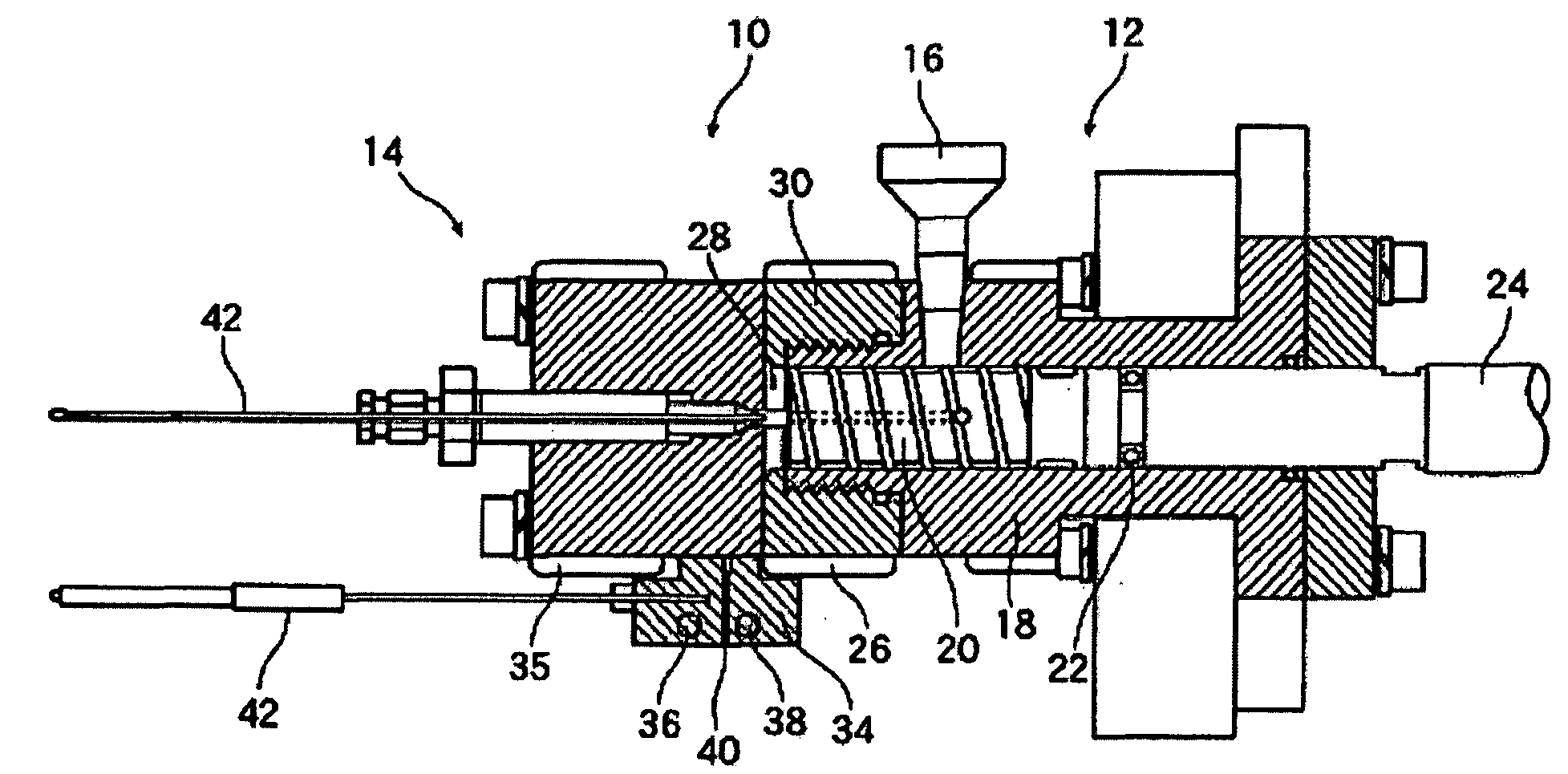
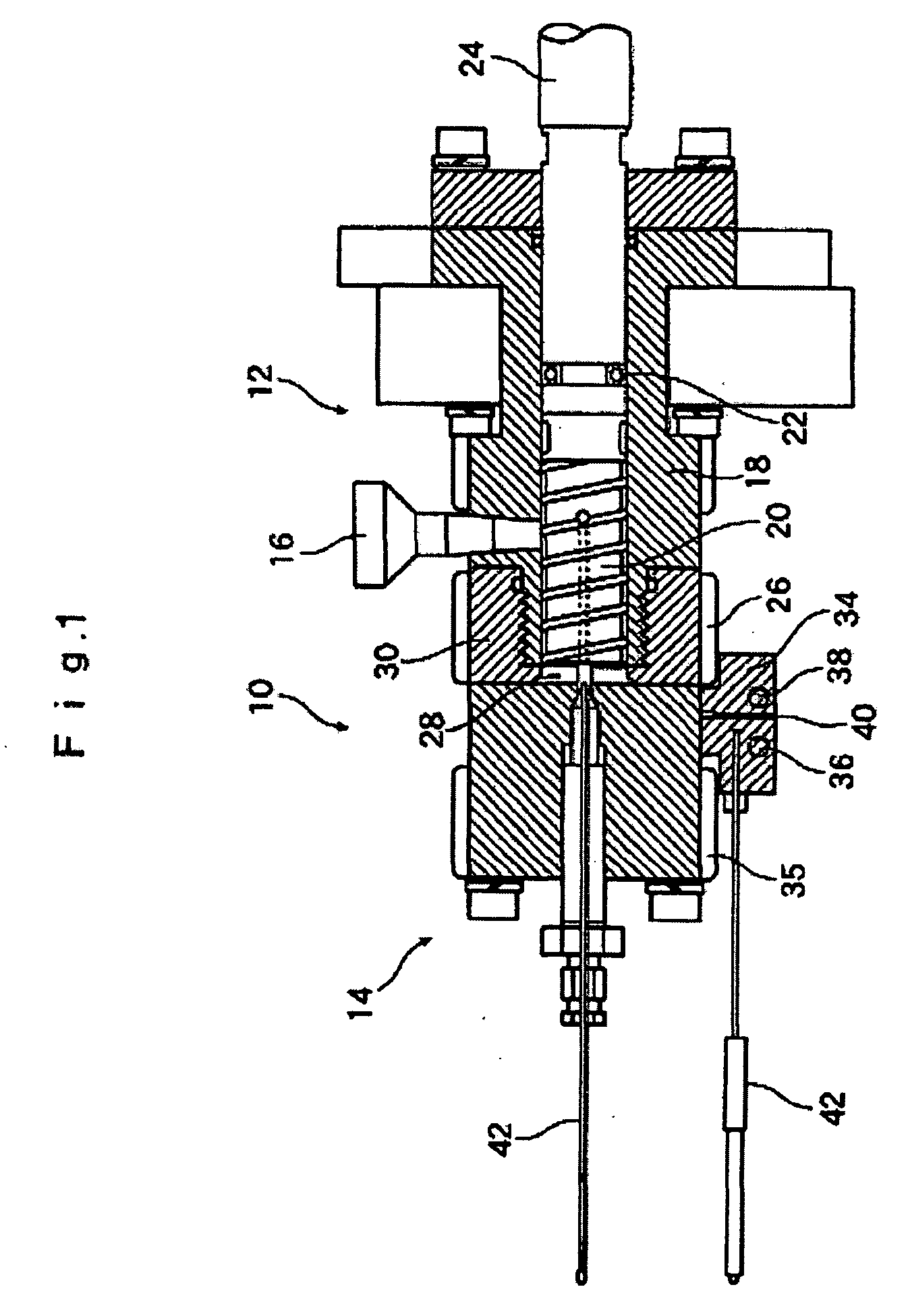
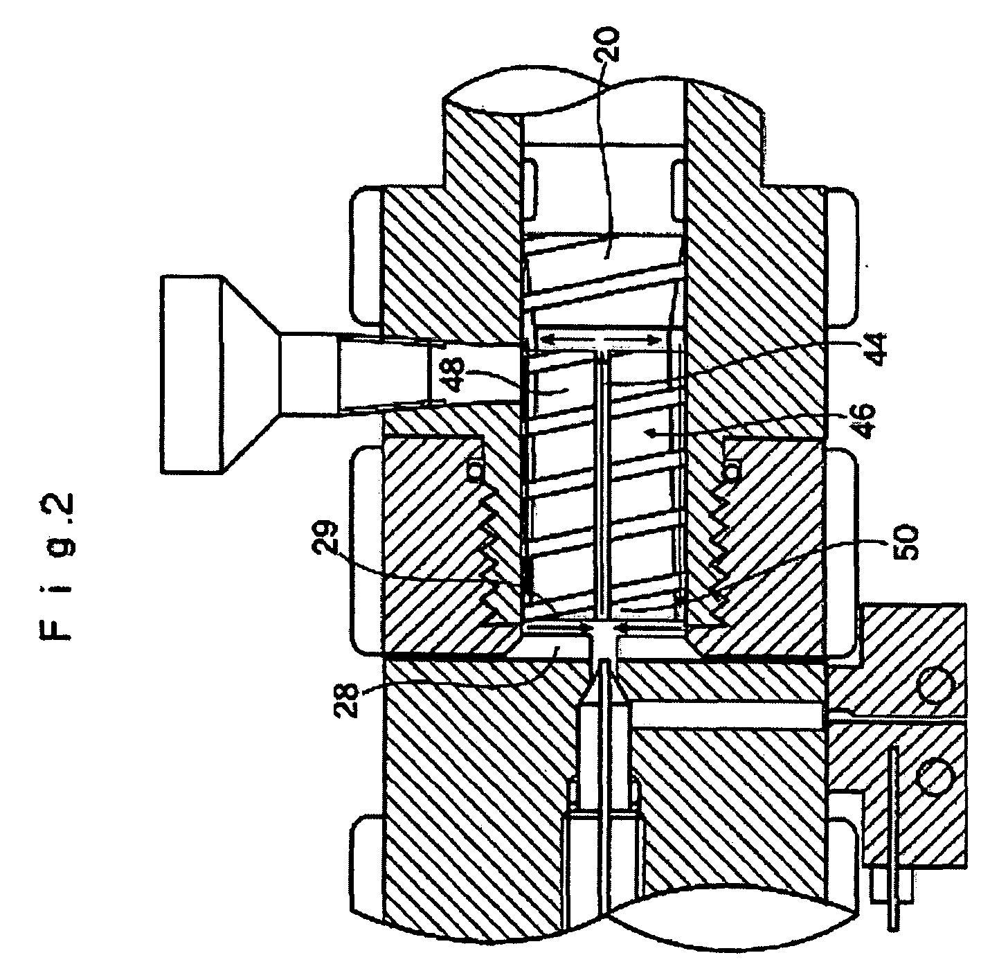
[0208]A melt-kneading apparatus using the aforementioned recirculation feedback screw 20 was used. The L / D ratio was 1.78. The screw rotation speed was 1000 rpm and corresponding shear speed was 1470 sec−1. The space was 1 mm and the product was taken out from the T-dies.

[0209]Sample Preparation

[0210]The multi-walled carbon nanotube (MWCNT) was not chemically processed. A PVDF / MWCNT composite was produced by processing for 4 minutes a...


PUM

PropertyMeasurementUnit
inner diameteraaaaaaaaaa
diameteraaaaaaaaaa

Abstract

A melt-kneading method for filling material and elastomer or resin, characterized in that a filling material constituted by a filler, and an elastomer or resin (thermoplastic resin or thermosetting resin), are introduced from a material introduction part at the end of a melt-kneading part having a cylinder with a screw and a heater, and the molten elastomer or resin and filling material constituted by a filler are kneaded under the conditions of 1000 to 3000 rpm in the rotation speed of the screw and 1500 to 4500 sec−1 in shear speed to feed the mixture from the rear edge to tip of the screw to be trapped in a space provided at the tip of the screw, after which the mixture is moved from the space to the rear edge of the screw through a hole provided at the center of the screw, with the cycle process performed for a specified period based on recirculation using the screw.

Description

BACKGROUND OF THE INVENTION[0001]1. Field of the Invention[0002]The present invention relates to a melt-kneading method for rubber, elastomer, thermoplastic resin or thermosetting resin whereby a filling material constituted by a nano-level filler is uniformly dispersed in a rubber, elastomer, thermoplastic resin or thermosetting resin. It also relates to a melt-kneaded product of rubber, elastomer, thermoplastic resin or thermosetting resin produced by uniformly dispersing a filling material constituted by a nano-level filler in a rubber, elastomer, thermoplastic resin or thermosetting resin, as well as a molded product constituted by such melt-kneaded product.[0003]2. Description of the Related Art[0004]Production methods for melt-kneaded products in which nano-level fillers such as fine silica grains, single-walled carbon nanotubes (SWCNT), multi-walled carbon nanotubes (MWCNT), carbon fibers (CF), carbon blacks (CB) and clay are uniformly dispersed, as well as melt-kneaded produ...

Claims


Application Information

Patent Timeline
Patent Type & Authority Applications(United States)
IPC IPC(8): B32B5/16B29B7/90C08L9/00
CPCC08J3/005C08J3/201C08J2321/00Y10T428/25Y10S977/742Y10S977/773C08J2327/16
Inventor SHIMIZU, HIROSHILI, YONGJIN
Owner NAT INST OF ADVANCED IND SCI & TECH
Why Eureka
Try Eureka