Such fuel tanks are typically buried underground or are otherwise not easy to access, for maintenance and monitoring applications such as taking an inventory of fuel quantity for determining fuel levels in the tank and for
leak detection, and characterizing
fuel quality for purposes of facilitating cleaning and removal tasks.
Inherent in the process of storing fuel are also known problems that relate to the accuracy of fuel-inventory measurements, generally and retaining
fuel quality, in particular.
For example, it has long been recognized that the presence of significant amounts of contaminant substances can affect the accuracy of determinations of volume of a fluid from liquid-level measurements.
In particular,
fuel storage tanks are susceptible to accumulation of water from the delivered product, condensation, damaged fill boxes, bad gaskets, loose fittings and various other non-water / vapor-tight openings.
Contamination of
petroleum-based fuels with water has been a commonly encountered difficulty since fuel tanks must be vented to allow replacement of volumes of fuel withdrawn from a tank with the ambient
atmosphere in order to avoid developing a partial vacuum in the tank.
Therefore, substantial quantities of
liquid water may accumulate in fuel tanks over a relatively short period of time.
This leads to the problems of raising the level of the surface of the fuel in the tank, and it causes the water to be trapped at the bottom of the tank since the water generally is non-soluble with the fuel.
Another known recurring problem associated with the sensing or measuring the level of fluid in a tank or other form of container, is that many of the fluids stored in the tank contain or are comprised of substances that leave or form deposits on the inner surfaces of the tank.
These deposits, if left untreated, can interfere with or prevent the accurate measurement or detection of the fluid levels.
It has a relatively short shelf-life and can degrade over time.
Thus, when fuel is stored, contaminants often settle out from the fuel.
Contaminants that are more dense than the fuel itself generally fall to the bottom of the
fuel tank, forming a non-uniform deposit of materials that build up progressively over time and are often referred to collectively as “
sludge.” Unfortunately, these processes occur where current
fuel supply lines are principally located—at the bottom of the tank.
As the
layers of sludge and water build towards the
fuel supply lines, it can artificially inflate the float-level readings which, in turn can lead to erroneous fuel-inventory measurements.
Further, if left untreated, the presence of the contaminants can adversely affect the fuel quality.
The fuel may even become un-pumpable and non-combustible, which could have catastrophic consequences to the
end user.
There are known problems and limitations encountered with such current systems, however, that limit their effectiveness in many applications.
For example, such systems are prone to provide erroneous results when the fuel contains contaminants such as sludge and water.
Further, the conventional systems cannot accurately characterize and display the properties of the various contaminants, such as the presence of microorganisms at the fluid-water interface or the formation of crystals from floating fatty acids, which are likely to develop in the
fuel storage tank.
As a result, such systems are self-limiting in an environment where multiple contaminants are present and the user must be able to quantify the contaminants for improvement of overall fuel quality.
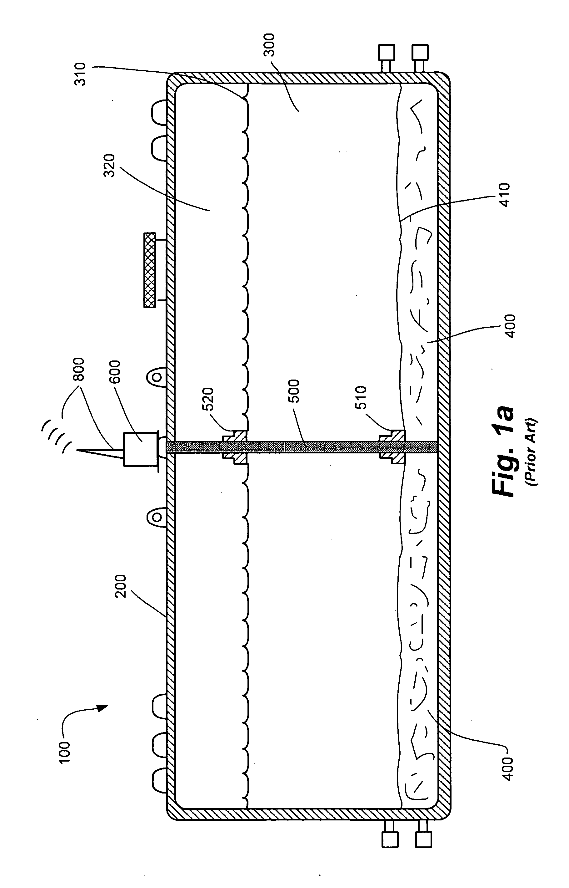
Despite their relative simplicity and ease of use, such conventional systems are known to suffer from certain disadvantages.
A significant
disadvantage commonly encountered is that the probes and floats conventionally used are susceptible to erroneous readings due to sludge that accumulates on the
rubber boots and
varnish that accumulates on the probe.
In particular, because the probes and floats are designed to report the levels of water and fuel, they generally cannot monitor
contamination such as sludge, micro organisms or free floating contaminants, and they cannot detect changes in
viscosity or density between materials in the fuel.
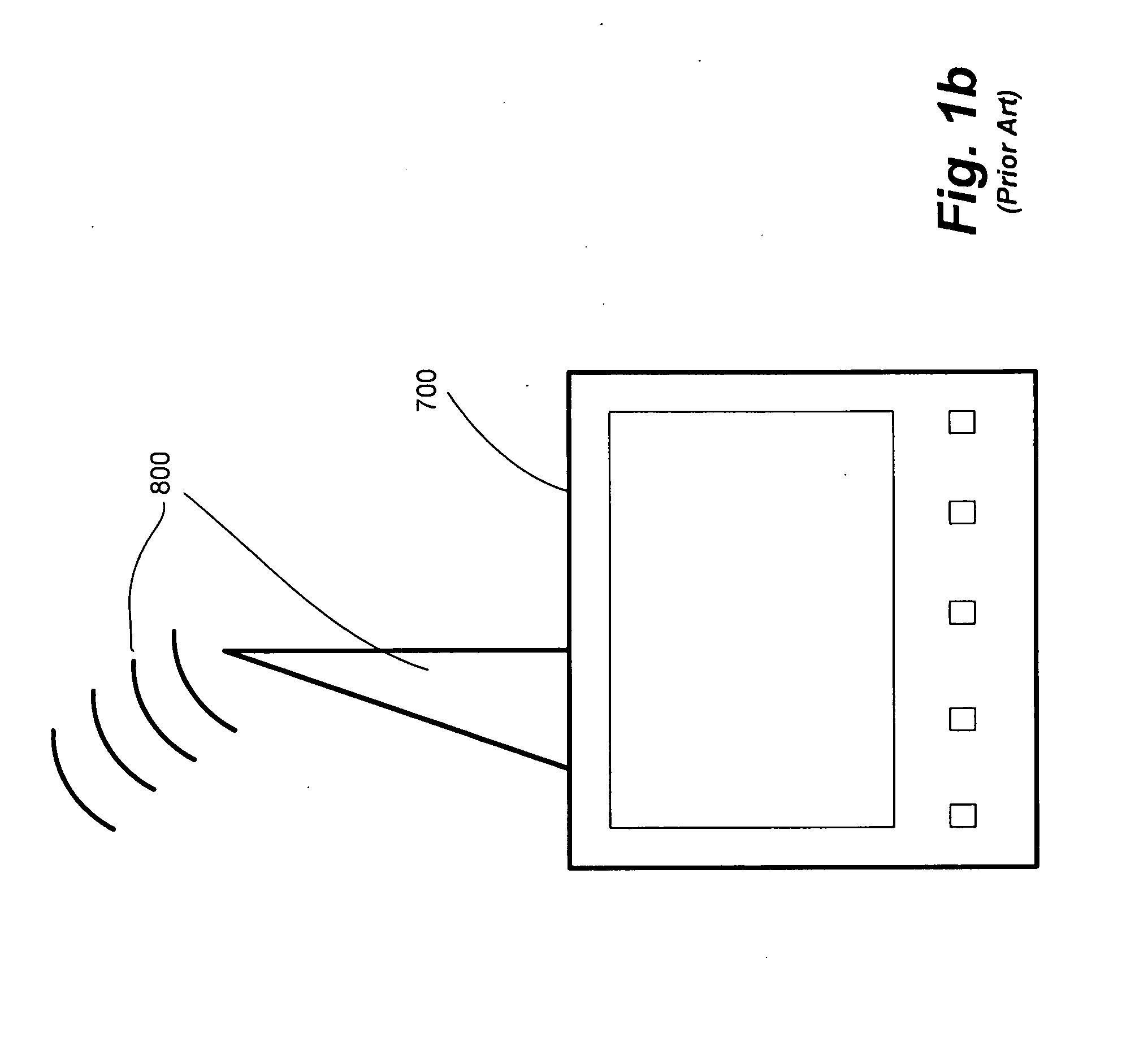
These readings are then reported to the display console in the form of erroneous float-level readings, which in turn results in erroneous determinations of fuel levels.
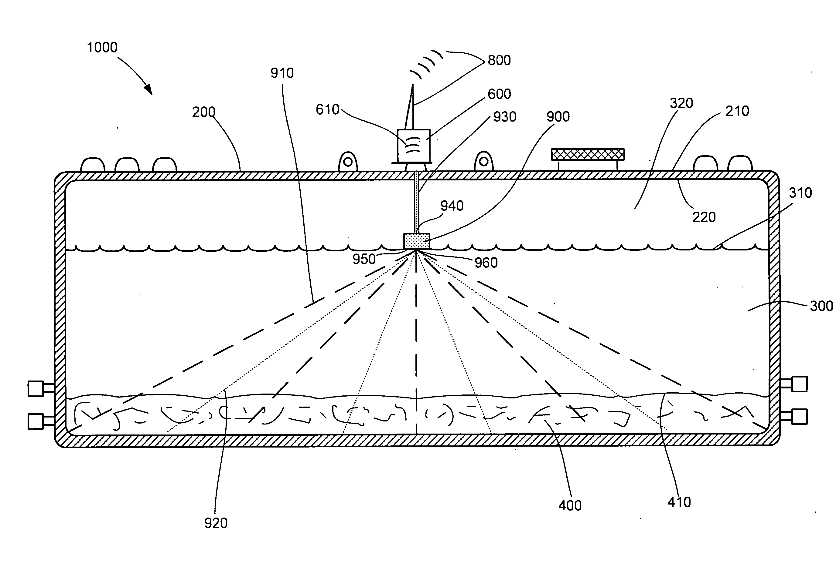
Another significant limitation of such systems is that the information reported to the display console generally does not provide visual references, for example, the
relative quantity of the various contaminants as compared with the fuel and water levels in the fuel tank.
Further, fuel quality is perhaps the single most important issue faced by alternative fuel producers, distributors and consumers.
However, the current storage and distribution infrastructure for handling mineral-based
petroleum products was not designed for the dynamics of alternative fuel constituents as they are introduced, substituted and diluted into the
system.
As environmental and economic pressures dictate the formulation of our fuels, and alternative fuel sources, in particular, there will be a negative
impact on the fuel handling infrastructure that will ultimately adversely affect fuel quality.
In particular, fuel storage tanks are susceptible to accumulation of water from the delivered product, condensation, damaged fill boxes, bad gaskets, loose fittings and various other non-water / vapor-tight openings.
Whether it is mineral or
biodiesel fuel, water adversely affects its quality.
Of course, such fuels are susceptible to the sludge build-up and other organic processes, such as described here and elsewhere, which can adversely affect fuel quality.
In addition to the foregoing problems that relate to the storage of all fuels, there are certain unique problems that can be associated with the storage of unconventional fuels, such as those with various fuel-additives that are now becoming more often used.
The problem with storing
ethanol-blended
gasoline is that if there is water present in the storage vessel, as there inevitably will be as discussed herein, the water will be absorbed into the blend.
Some of the problems associated with
biodiesel include the formation of white flakes or sediments at the bottom of the fuel tank that are mostly monoglycerides or saturated fatty acids produced from an incomplete reaction or the improper washing of the fuel.
These precipitants will plug filters and ultimately can become unpumpable, which again is potentially damaging to the engine.
Thus, it will add to the diminished quality of fuel at the bottom of the tank.

