Brushless DC Motor with Reduced Current Ripple

US20090128070A1Inactive Publication Date: 2009-05-21LTI HLDG INC

Image

  • Brushless DC Motor with Reduced Current Ripple
  • Brushless DC Motor with Reduced Current Ripple
  • Brushless DC Motor with Reduced Current Ripple

Examples


Embodiment Construction

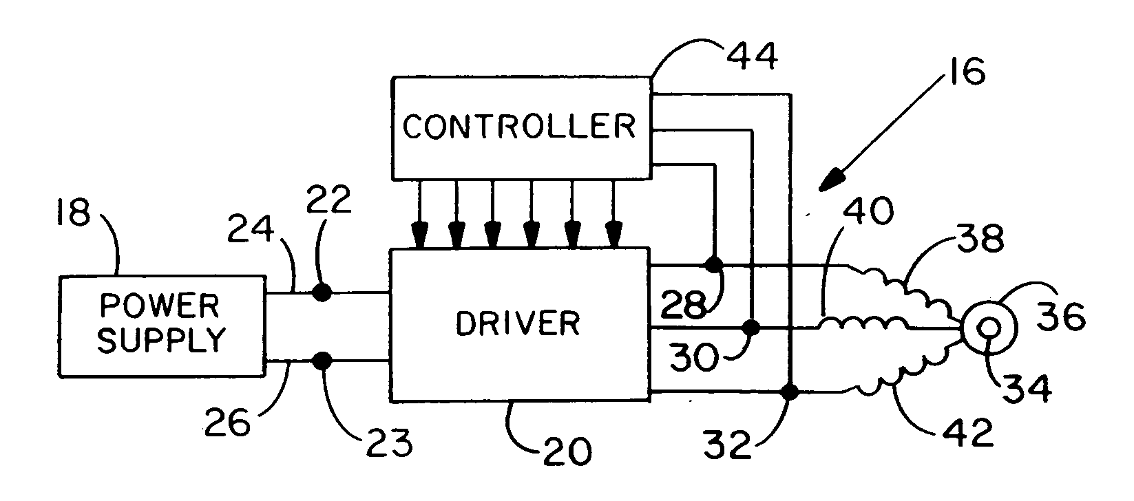
[0040]With further reference to the drawings, FIG. 5 shows a system 16 for coupling a 3-phase brushless DC motor to a DC power supply 18. System 16 includes a commutation circuit or driver 20 having input terminals 22 and 23 coupled respectively to a high voltage line 24 and low voltage line 26 of the power supply. Driver 20 has several output terminals 28, 30 and 32 coupled to the motor. The motor includes a rotor 34 surrounded by a stator 36 and supported for rotation relative to the stator through selective driving of stator windings 38, 40 and 42 which represent angularly separated phases A, B, and C of the motor. Driver output terminals 28, 30 and 32 are coupled respectively to stator windings 38, 40 and 42.

[0041]System 16 further includes a controller 44, preferably a microprocessor, for controlling driver 20 to selectively and alternatively apply the high voltage and the low voltage individually to stator windings 38, 40 and 42. Controller 44 further is coupled to output term...


PUM


Abstract

A commutation circuit for driving a brushless DC motor is controlled according to a commutation cycle composed of alternating primary steps and transitional steps. The commutation circuit includes pairs of field effect transistors coupled in series between the high voltage and low voltage terminals of a DC power supply. Output terminals between each pair of transistors are individually coupled to the phases of a DC motor. A controller operates the commutation circuit to selectively set the phases at active and inactive states. The controller further employs a plurality of voltage control functions individually associated with the motor phases to selectively modulate the voltage applied to one of the phases during the active states, to provide transitional steps in the commutation cycle during which the applied voltage is modulated to reduce its magnitude with respect to the high voltage or the low voltage.

Description

BACKGROUND OF THE INVENTION[0001]The present invention relates to electrically commutated motors, and more particularly to controllers and drivers for trapezoidally commutated motors.[0002]Brushless electronically commutated motors have been utilized increasingly in lieu of brushed DC motors in numerous applications, primarily for their advantages of lower cost, higher efficiency, and longer useful life. Electronically commutated motors and drivers generally are provided in two types: sinusoidally commutated motors and trapezoidally commutated motors.[0003]Sinusoidally commutated motors, also known as permanent magnet AC synchronous motors, have a back EMF (electromotive force) waveform similar to a sine wave. In a three-phase motor, all phases are driven simultaneously at different voltages that vary substantially sinusoidally. Separate position sensors, e.g. Hall effect sensors, are required to provide the necessary rotor position information to the electronic drive.[0004]Trapezoi...

Claims


Application Information

Patent Timeline
21 May 2009
Publication
US20090128070A1
IPC
H02P6/14; H03K5/00; H02P6/18
CPC
H02P6/002; H02P2209/07; H02P6/16; H02P6/28
Inventors
BROWN, ROBERT G.