
High Pressure/High Temperature Magnetic Resonance Tool

Inactive Publication Date: 2009-05-21
SCHLUMBERGER TECH CORP
View PDF14 Cites 33 Cited by
  • Summary
  • Abstract
  • Description
  • Claims
  • Application Information

AI Technical Summary

Benefits of technology

[0038]The foregoing has outlined rather broadly the features and technical advantages of the present invention so that the detailed description of the invention may be better understood. Additional features and advantages of the invention will be described hereinafter which form the subject of the claims of the invention. It should be appreciated by those skilled in the art that the conception and specific embodiments disclosed may be readily utilized as a basis for modifying or designing other structures for carrying out the same purposes of the present invention. It should also be realized by those skilled in the art that such equivalent constructions do not depart from the scope of the invention as set forth in the appended claims.

Problems solved by technology

This type of pressure cell is not, however, viable for use in a downhole fluid sampling tool because it is incapable of operating at the elevated temperatures and pressures encountered in a wellbore.
The low fill factor is problematic because the signal-to-noise ratio (S / N) of the NMR measurement is directly proportional to the fill factor.
Another problem with the prior art pressure cell is that it requires pressure compensation, as described above, which adds to the complexity, cost, and maintenance of the tool.
The NMR magnet, flow pipe, and associated antennas disclosed in the '245 patent, however, are not capable of making NMR diffusion measurements, and are not suitable for the high pressure and temperature environment encountered by borehole fluid sampling tools.
Those materials do not have the strength to withstand the pressures encountered in typical downhole environments.
The attenuation caused by metallic or highly conductive steel flowlines causes severe signal-to-noise ratio problems for measurements made by EM sensors situated outside of the flowline.
However, in practice it is difficult to manufacture this magnet and small deviations of the directions of the magnetization or field strength from those prescribed by theory can result in a substantial gradient in the magnetic field in the region of the flowline.
For example, prior art magnet designs that have magnets surrounding the flowline do not provide space for “thru-wires”.
Moreover, prior art designs do not provide for continuous flow within or through the sampling tool when NMR measurements are desired on a stationary sample.

Method used


Image

  • High Pressure/High Temperature Magnetic Resonance Tool
  • High Pressure/High Temperature Magnetic Resonance Tool
  • High Pressure/High Temperature Magnetic Resonance Tool

Examples


Embodiment Construction

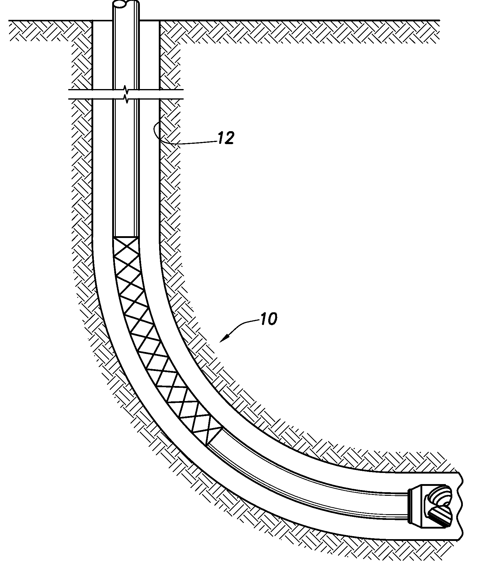
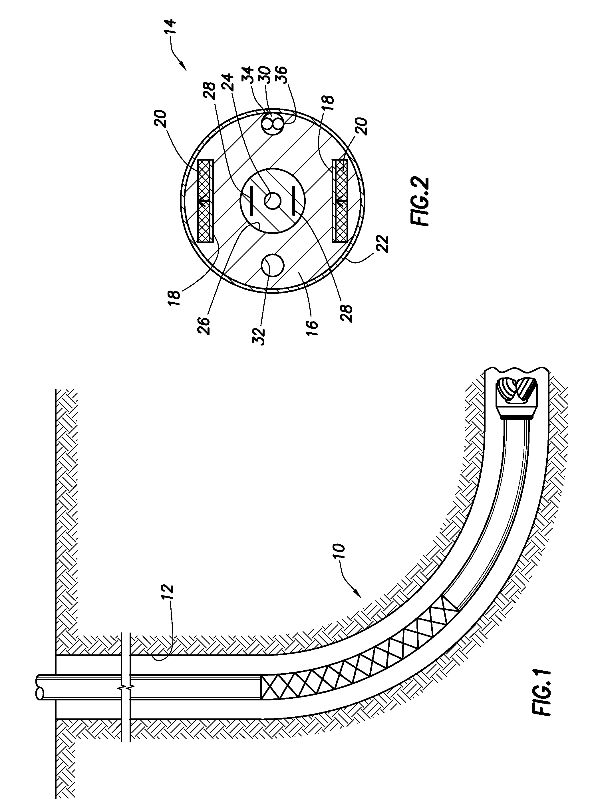
[0017]FIG. 1 shows a magnetic resonance tool 10 disposed in a wellbore 12. The tool could be a nuclear magnetic resonance tool or an electron spin resonance tool. Also, although the particular embodiment shown is in a wellbore, the invention is not limited to downhole applications and may be used in a laboratory. While one embodiment of this invention provides for a NMR instrumented flowline section that can be used in a logging tool, the same apparatus can also be used as a high pressure cell for conducting laboratory NMR measurements on reservoir or process fluids. “Process fluids” are any of the intermediate or final fluids resulting from performing a process. The invention may be used in wireline logging or while-drilling.

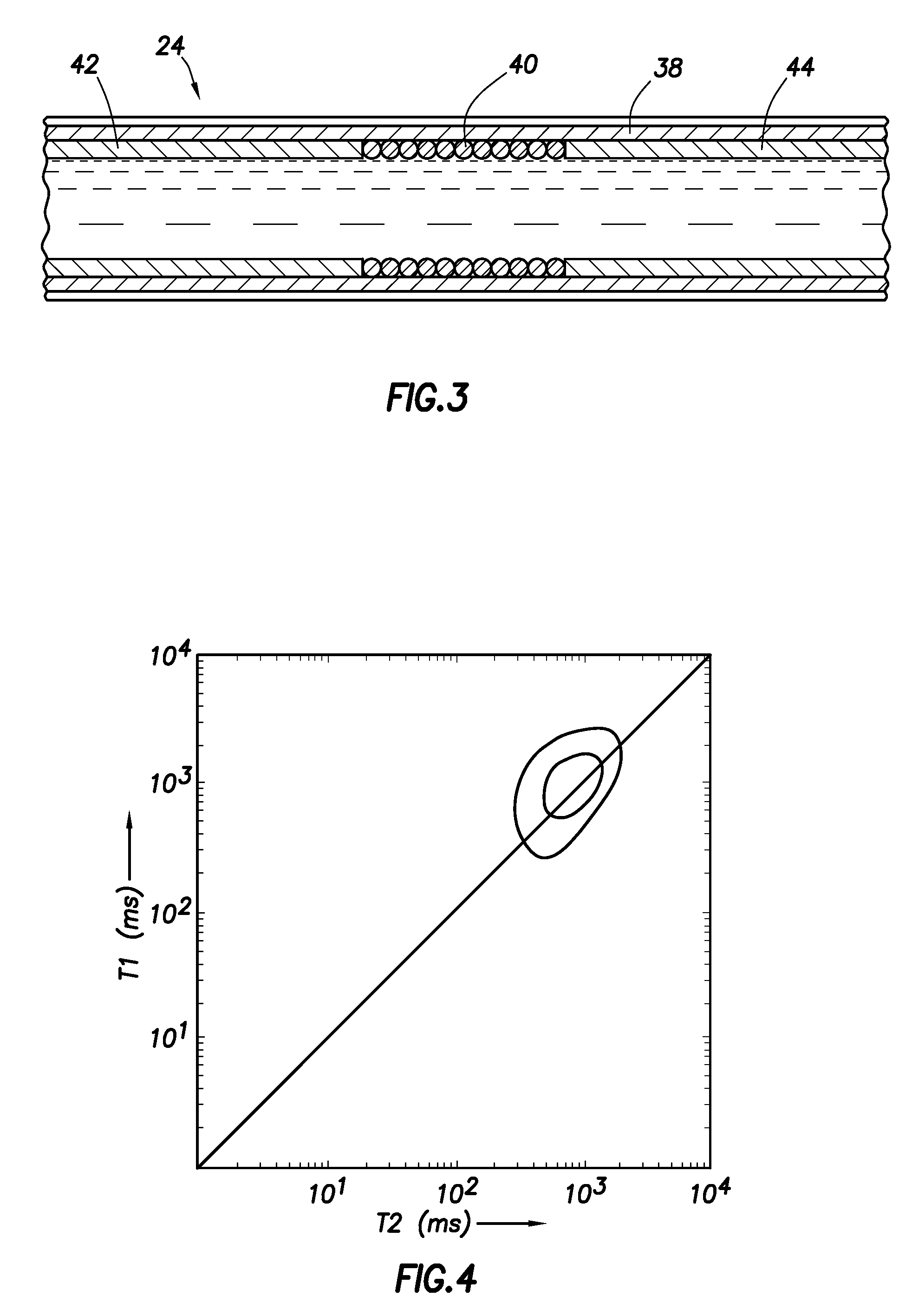
[0018]FIG. 2 discloses a NMR module having a magnet assembly 14 that can be used to perform NMR spin echo measurements to determine, for example, relaxation time and diffusion coefficient distributions of reservoir fluids. The fluids of interest may be in a lab...


PUM


Abstract

The present invention pertains to an apparatus and method for conducting magnetic resonance measurements on fluids at high pressures and / or high temperatures. The apparatus can be used in conjunction with or as part of a downhole fluid sampling tool to perform NMR measurements on fluids withdrawn from petroleum reservoirs, or can also be used for laboratory measurements on live reservoir fluids. The apparatus can perform all of the measurements made by modern NMR logging tools, including multi-dimensional distribution functions of spin-spin (T2) and spin-lattice relaxation (T1) times and molecular diffusion coefficients. The spin densities of hydrogen and other NMR sensitive species can be computed from the distribution functions. The apparatus can also be used to predict the apparent conductivity of the fluids in the flowline from measurements of the quality factor (“Q”) of the NMR circuit. The apparent conductivity can be used to predict water cut or water salinity.

Description

TECHNICAL FIELD[0001]The present invention pertains to making NMR (nuclear magnetic resonance) or ESR (electron spin resonance) measurements on fluids that are at high pressure and / or high temperature.BACKGROUND OF THE INVENTION[0002]In the field of hydrocarbon exploration, measurements are often made on reservoir fluids. Such measurements are typically made to obtain information on different reservoir fluid properties, e.g., resistivity, NMR, optical absorption and scattering, dielectric constant, etc. Measurements may be made on fluids in the formation or in a flowline of a fluid sampling tool. Fluid sampling tools are widely used in the well-logging industry. Borehole fluid sampling tools have one or more probes that are pressed against the borehole wall so that reservoir fluids can be pumped out of the earth formation into a flowline or sample bottle situated in the fluid sampling tool. A sample placed in a sample bottle may be preserved so that it may be tested in a laboratory ...

Claims


Application Information

Patent Timeline
IPC IPC(8): G01V3/32
CPCG01N24/081G01R33/305G01R33/307G01R33/60G01R33/3806G01R33/383G01R33/34053
Inventor FREEDMAN, ROBERTGANESAN, KRISHNAMURTHYGRANT, DOUGLAS W.
Owner SCHLUMBERGER TECH CORP
Learn More