Prosthetic Heart Valves, Support Structures and Systems and Methods for Implanting the Same

a heart valve and prosthesis technology, applied in the field of medical devices and methods, can solve the problems of increased risk of blood clot, low radial stiffness, and a long recovery period, and achieve the effects of enhancing the sealing of the support structure, preventing migration, and improving tissue adheren

Inactive Publication Date: 2009-05-21
AORTX
View PDF100 Cites 200 Cited by
  • Summary
  • Abstract
  • Description
  • Claims
  • Application Information

AI Technical Summary

Benefits of technology

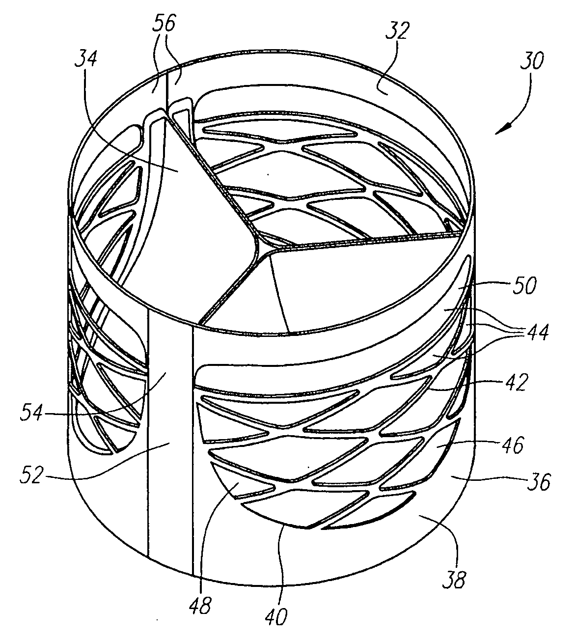
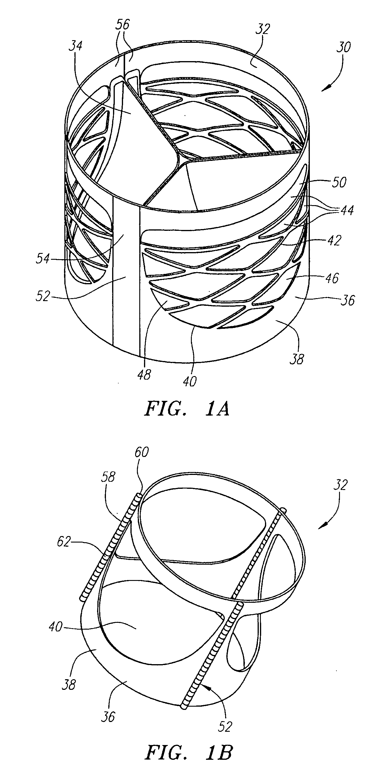
[0021]The support structure may be provided with one or more anchoring members that are adapted to engage the internal wall of the body lumen. Each anchoring member may comprise a barb, a tooth, a hook, or any other member that protrudes from the external surface of the support structure to physically engage the internal wall of the body lumen. Alternatively, the anchoring member may comprise an aperture formed in the support structure that allows tissue to invaginate therethrough, i.e., the outward radial force of the support member against the vessel wall causes the frame portion of the support member to slightly embed into the vessel wall, thereby causing some of the tissue to penetrate through the aperture into the interior of the support member. The tissue invagination acts to anchor the support structure in place. An anchoring member may be selectively engageable, such as by an actuator, or it may be oriented so as to be permanently engaged. Alternatively, the anchoring member may be self-actuating, or it may be deployed automatically during deployment of the support member. In one embodiment, a plurality of small apertures in the panel surface of the support member are arranged in a gradient, where the density of apertures is greater at one end of the support member relative to the density of apertures at the other end of the support member. The gradient of ape...

Problems solved by technology

The main problem with all mechanical valves is the increased risk of blood clotting.
Such open heart surgery is particularly invasive and involves a lengthy and difficult recovery period.
Although this type of design can provide for crimpability, it provides little radial stiffness.
The recoil is due in part because of the stiffness mismatches between the device and the anatomical environment in which it is placed.
These devices also commonly cause crushing, tearing, or other deformation to the valve leaflets during the contraction and expansion procedures.
This type of design provides high radial stiffness, yet crimping results in large material strains that can cause stress fractures an...

Method used


Image

  • Prosthetic Heart Valves, Support Structures and Systems and Methods for Implanting the Same
  • Prosthetic Heart Valves, Support Structures and Systems and Methods for Implanting the Same
  • Prosthetic Heart Valves, Support Structures and Systems and Methods for Implanting the Same

Examples


Embodiment Construction

[0175]Before the present invention is described, it is to be understood that this invention is not limited to particular embodiments described, as such may, of course, vary. It is also to be understood that the terminology used herein is for the purpose of describing particular embodiments only, and is not intended to be limiting, since the scope of the present invention will be limited only by the appended claims.

[0176]Unless defined otherwise, all technical and scientific terms used herein have the same meaning as commonly understood by one of ordinary skill in the art. Although any methods and materials similar or equivalent to those described herein can also be used in the practice or testing of the present invention, the preferred methods and materials are now described. All publications mentioned herein are incorporated herein by reference to disclose and describe the methods and / or materials in connection with which the publications are cited.

[0177]It must be noted that as us...


PUM


Abstract

Prosthetic valves and their component parts are described, as are prosthetic valve delivery devices and methods for their use. The prosthetic valves are particularly adapted for use in percutaneous aortic valve replacement procedures. The delivery devices may be adapted for use in minimally invasive or endovascular surgical procedures.

Description

RELATED APPLICATION[0001]This application is a continuation-in-part of U.S. application Ser. No. 11 / 469,771, filed Sep. 1, 2006, which is continuation of U.S. application Ser. No. 11 / 425,361, filed Jun. 20, 2006, which is a continuation-in-part of U.S. application Ser. No. 11 / 066,126, filed Feb. 25, 2005, which is related to U.S. Application Ser. No. 60 / 548,731, filed Feb. 27, 2004, all of which are fully incorporated herein by reference for all purposes.FIELD OF THE INVENTION[0002]The present invention relates generally to medical devices and methods. More particularly, the present invention relates to an implantable medical device (e.g., prosthetic heart valves, etc.) and other structures for providing scaffolding in body lumens. Devices and methods for delivering and deploying implantable devices and scaffolding structures are also disclosed herein.BACKGROUND INFORMATION[0003]Medication may be used to treat some heart valve disorders, but many cases require replacement of the nat...

Claims


Application Information

Patent Timeline
IPC IPC(8): A61F2/24A61B19/00
CPCA61F2/2415A61F2/2418A61F2/2433A61F2/2436A61F2/2439A61F2230/005A61F2220/0016A61F2220/005A61F2220/0058A61F2220/0091A61F2220/0008
Inventor ROTH, ALEX T.FORSTER, DAVID C.WALSH, BRANDON G.BECKEY, BRIANHENEVELD, SCOTTGINN, RICHARD S.
Owner AORTX
Why Eureka
Try Eureka