System and Method for Focused Ion Beam Data Analysis

a focused ion beam and data analysis technology, applied in the field of charged particle beam systems, can solve the problems of erroneous analysis of modified devices, older fib systems operating on current state-of-the-art semiconductor devices do not provide image and graphical information with a sensitivity that is usable by operators, and real-time image may not provide any value for fib operators for endpoint detection, etc., to achieve the effect of improving the sensitivity to changes

Active Publication Date: 2009-05-28
DCG SYST
View PDF5 Cites 53 Cited by
  • Summary
  • Abstract
  • Description
  • Claims
  • Application Information

AI Technical Summary

Benefits of technology

[0020]It is an object of the present invention to obviate or mitigate at least one disadvantage of previous endpoint detection schemes. In particular, it is an object of the present invention to generate images and endpoint graphs having improved sensitivity to changes.
[0023]In further embodiments, the method includes a step of generating a differential display image from a difference between current raster data and a predetermined number of previous raster data, wherein each of the predetermined number of previous raster data is weighted by decreasing percentages. The image palette can include multiple colors which are effective for increasing the perception of changes in the resultant raster image compared to a greyscale palette.
[0029]In other embodiments of the present aspect, the information from each frame generated by the CPB system, and CPB system operating parameters can be stored for subsequent retrieval and processing according to the steps of processing and plotting. The step of plotting can include re-scaling the y-axis to a new range which includes all summed dwell point intensity values over the range of the x-axis displayed on the endpoint graph, for increasing ease of perception in determining when changes in the summed dwell point intensity values are occurring.

Problems solved by technology

Unfortunately, a FIB operator is responsible for halting the milling process when a metal line of interest has been sufficiently exposed or completely cut, a process known as “endpointing”.
Imprecise endpointing can lead to erroneous analysis of the modified device.
Older FIB systems operating on current state-of-the-art semiconductor devices do not provide image and graphical information with a sensitivity that is usable by the operator.
Due to the small image area and a reduced level of electron detection, the real-time image may not provide any value for the FIB operator for endpoint detection since changes in the image would be very difficult to visually detect.
Furthermore, some FIB systems execute data preprocessing, such as dithering, which in fact reduces an operators' level of confidence in determining proper endpointing for state-of-the-art semiconductor devices.
One difficulty in the present scheme arises from plotting the data on a fixed scale, such as the 8-bit (0-255) scale found on many instruments, that does not dynamically rescale to show more sensitive changes.
A larger difficulty arises from the fact that the present system bases its analysis on the 100 pixel data points described above that result from the fact that the data is displayed on a 10 pixel×10 pixel area, even though the actual number of dwell points is 21×21=441.
Accordingly, there is a lower probability of successful endpoint detection by the FIB operator, and a lower probability of successful design verification, leading to no data on the success of a new design, or worse erroneous results that may lead to incorrect design changes being propagated into the final device.
New FIB systems calibrated for state-of-the-art devices may be available, but the cost of replacing older FIB systems is prohibitive.
Modification of the FIB system firmware or hardware is generally prohibited, since FIB system modification voids certification of the system and any manufacturer warranties.
In SIMS, not such requirement exists, and in fact it is often a requirement that SIMS be performed on a device that is not complete (typically just a bare silicon die with no conductor layers fabricated) and therefore cannot operate.
Additionally, as devices become more complex, the number of operations required to perform successful microsurgery typically increases, as do the complexity of these operations.
The difficulty arises in more complex circuit edit tasks, in determining if the unexpected function is due to a flaw in the design or an error in how the design was implemented through microsurgery.
As time passes and other microsurgery tasks are performed it is difficult for the operator to recall every element of a particular surgery, and even if the test results are obtained very quickly after completion of the surgery, it is not possible for all operators to recall all aspects of the task.

Method used


Image

  • System and Method for Focused Ion Beam Data Analysis
  • System and Method for Focused Ion Beam Data Analysis
  • System and Method for Focused Ion Beam Data Analysis

Examples


Embodiment Construction

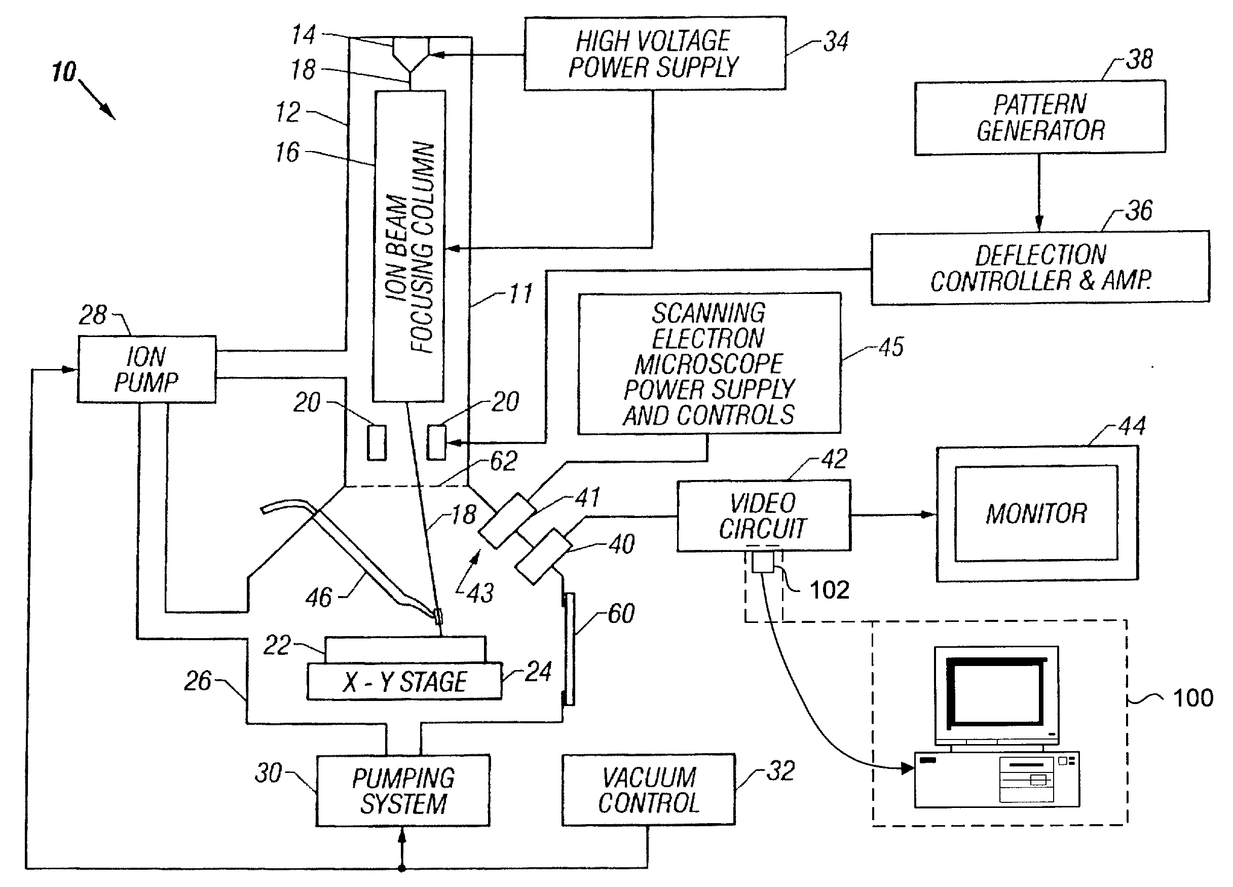
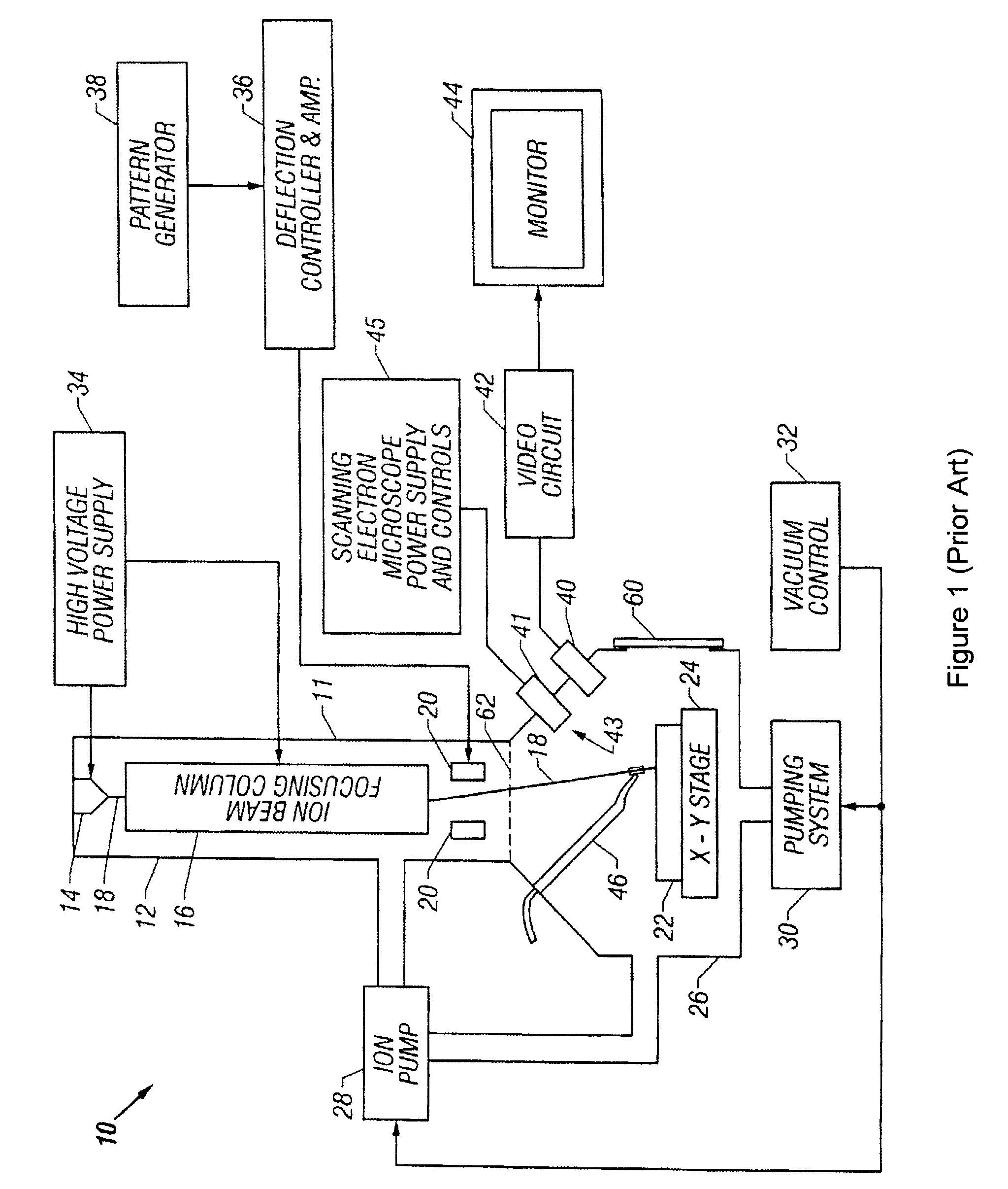
[0050]Generally, the present invention provides methods for improving FIB milling endpointing operations. The methods involve generating real-time images of the area being milled and real-time graphical plots of pixel intensities with an increased sensitivity over native FIB system generated images and plots. The images and plots are generated with raw signal data obtained from the native FIB system. More specifically, the raw signal data is processed according to specific algorithms for generating images and corresponding intensity graphs which can be reliably used for accurate endpointing. In particular, the displayed images will display more visual information regarding changes in milled material, while the intensity graphs will plot pixel intensity data on a dynamically adjusting scale to dramatically highlight relative changes in milled material, as well as interpreting all dwell point data produced by the system rather than a subset, as in the current state of the art systems....


PUM


Abstract

A system and method for improving FIB milling endpointing operations. The methods involve generating real-time images of the area being milled and real-time graphical plots of pixel intensities with an increased sensitivity over native FIB system generated images and plots. The images and plots are generated with raw signal data obtained from the native FIB system. More specifically, the raw signal data is processed according to specific algorithms for generating images and corresponding intensity graphs which can be reliably used for accurate endpointing. In particular, the displayed images will display more visual information regarding changes in milled material, while the intensity graphs will plot aggregate pixel intensity data on a dynamically adjusting scale to dramatically highlight relative changes in milled material.

Description

FIELD OF THE INVENTION[0001]The present invention generally relates generally to charged particle beam systems. In particular, the present invention relates to an apparatus and system for processing signal data from focused ion beam FIB systems.BACKGROUND OF THE INVENTION[0002]Focused Ion Beam (FIB) microscope systems have been produced commercially since the mid 1980's, and are now an integral part of rapidly bringing semiconductor devices to market. FIB systems produce a narrow, focused beam of charged particles, and scan this beam across a specimen in a raster fashion, similar to a cathode ray tube. Unlike the scanning electron microscope, whose charged particles are negatively charged electrons, FIB systems use charged atoms, hereinafter referred to as ions, to produce their beams. These ions are, in general, positively charged.[0003]These ion beams, when directed onto a semiconductor sample, will eject secondary electrons, secondary ions (i+ or i−), and neutral molecules and at...

Claims


Application Information

Patent Timeline
Patent Type & Authority Applications(United States)
IPC IPC(8): B41J2/435
CPCG01N1/286G01N2001/2873H01J37/304H01J37/3056H01J2237/31749H01J2237/30466H01J2237/30483H01J2237/31745H01J2237/221H01J37/26H01L21/265
Inventor PHANEUF, MICHAEL WILLIAMANDERSON, MICHAEL ANTHONYLAGAREC, KEN GUILLAUME
Owner DCG SYST
Why Eureka
Try Eureka