Metal-Based Composite Material Containing Both Micron-Size Carbon Fiber and Nano-Size Carbon Fiber

Inactive Publication Date: 2009-05-28
SHIMANE PREFECTURAL GOVERNMENT MATSUE
View PDF2 Cites 50 Cited by
  • Summary
  • Abstract
  • Description
  • Claims
  • Application Information

AI Technical Summary

Benefits of technology

[0024]The present invention allows improvements in the thermal conductivity in the direction perpendicular to the micron-size carbon fiber, the thermal expansion coefficient and the like, which have been drawbacks to conventional metal-b

Problems solved by technology

In addition, as electronic devices have decreased in size and weight, he

Method used


Image

  • Metal-Based Composite Material Containing Both Micron-Size Carbon Fiber and Nano-Size Carbon Fiber
  • Metal-Based Composite Material Containing Both Micron-Size Carbon Fiber and Nano-Size Carbon Fiber
  • Metal-Based Composite Material Containing Both Micron-Size Carbon Fiber and Nano-Size Carbon Fiber

Examples


example 1

[0120]An example of a composite material containing aluminum, a vapor-grown carbon nanofiber, and a pitch-based carbon fiber is described.

[0121]An aluminum powder (manufactured by Showa Denko; average particle size: 5 μm), a vapor-grown carbon nanofiber (hereinafter “VGCF”, manufactured by Showa Denko; diameter: 150 nm; aspect ratio: 60 or more), and a pitch-based carbon fiber (diameter: 10 μm; 2000 fiber bundles) were used.

[0122]80 cc of isopropanol was added to 47.5 g of the aluminum powder and 2.5 g of VGCF and mixed for 1 hour using an ultrasonic mixer to yield an aluminum-nanofiber mixture.

[0123]Fiber bundles of the pitch-based carbon fiber were immersed in the thus-obtained suspension to allow the aluminum-nanofiber mixture to adhere to the fiber bundles.

[0124]The resulting material was air-dried for 24 hours. As a result, a fiber adhered with the metal powder and the nano-size carbon fiber containing 33.3 wt % of the aluminum powder, 1.7 wt % of VGCF, and 65 wt % of the pitch...

example 2

[0128]An example of a composite material containing aluminum and a vapor-grown carbon nanofiber is described.

[0129]An aluminum powder (manufactured by Showa Denko; average particle size: 5 μm), a vapor-grown carbon nanofiber (hereinafter “VGCF”, manufactured by Showa Denko; diameter: 150 nm; aspect ratio: 60 or more), and a pitch-based carbon fiber (diameter: 10 μm; 2000 fiber bundles) were used.

[0130]80 cc of isopropanol was added to 42.5 g of the aluminum powder and 7.5 g of VGCF and mixed for 1 hour using an ultrasonic mixer.

[0131]The resulting material was air-dried for 24 hours. As a result, a mixed powder containing 75 wt % of the aluminum powder and 15 wt % of VGCF was obtained.

[0132]The resulting mixed powder was charged into a graphite sintering die with a 20×20 mm square cross-section. The die was sintered using a pulsed electric current sintering apparatus in a vacuum of 10 Pa, at a pressure of 50 MPa and a sintering temperature of 600° C., to yield a composite material. ...

example 3

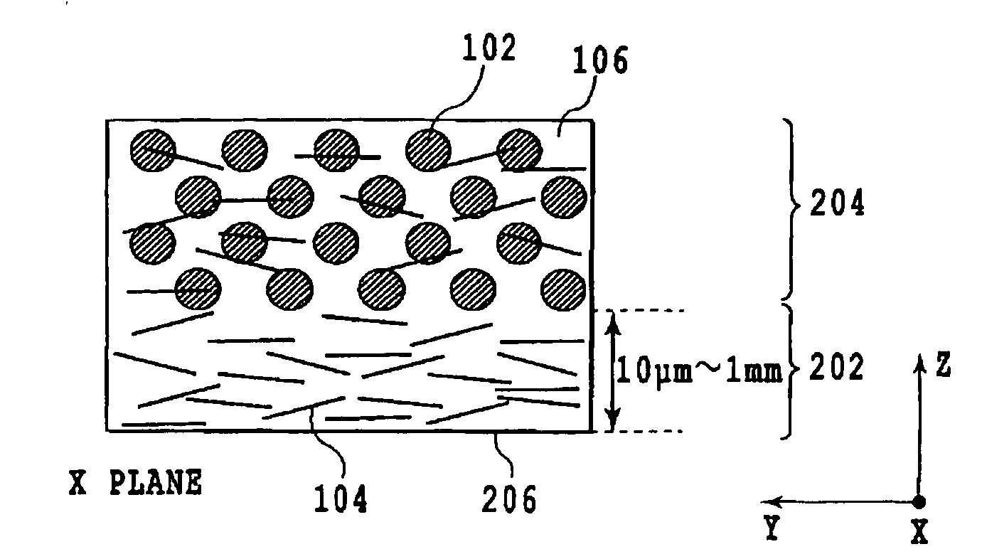
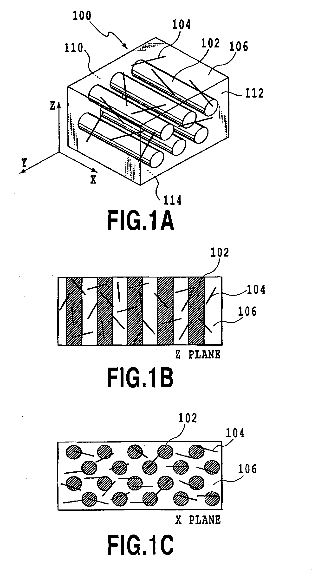
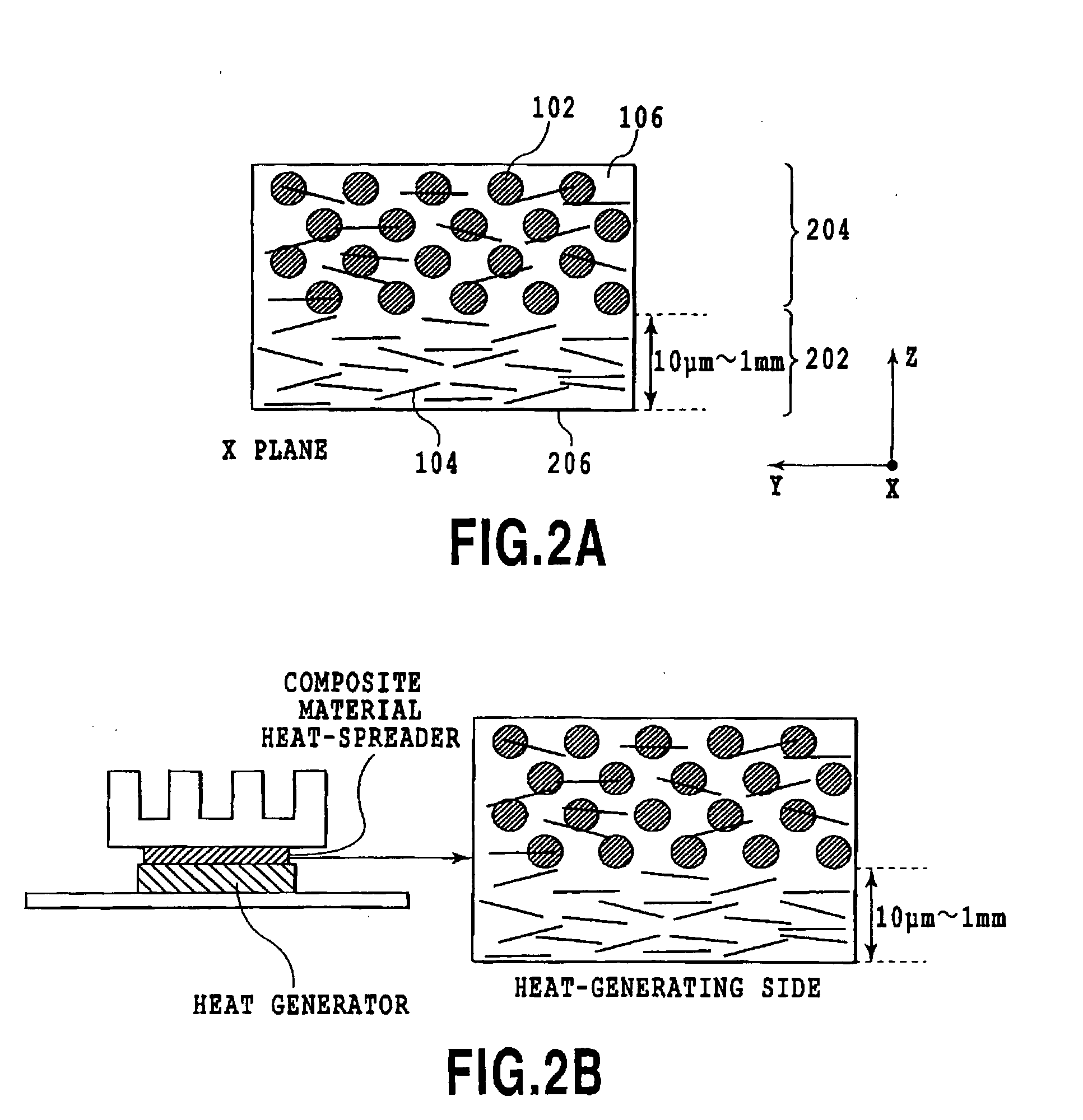
[0134]The composite materials obtained in the aforementioned Examples 1 and 2 were charged into a graphite sintering die with a 20×20 mm square cross-section. The die was sintered using a pulsed electric current sintering apparatus in a vacuum of 10 Pa, at a pressure of 50 MPa and a sintering temperature of 600° C., to yield a composite material having a surface region that is free of the micron-size carbon fiber. The resulting composite material was a composite material with layers that exhibit the properties obtained according to Examples 1 and 2, respectively.


PUM

PropertyMeasurementUnit
Lengthaaaaaaaaaa
Lengthaaaaaaaaaa
Fractionaaaaaaaaaa

Abstract

An object of the present invention is to provide a metal-based carbon fiber composite material that exhibits an improved thermal expansion coefficient and an improved thermal conductivity, and is smaller in weight. The metal-based carbon fiber composite material of the present invention comprises a metal and a carbon fiber comprising a micron carbon fiber and a nanofiber; the composite material having a first surface; the micron-size carbon fiber being oriented in one direction parallel to the first surface of the composite material, and being continuous from one end to the other end; at least 80% of the nanofiber being oriented at an angle within 30° with respect to the first surface; and the nano-size carbon fiber being oriented randomly in a plane parallel to the first surface. In the metal-based carbon fiber composite material, a surface region thereof may comprise a smaller amount of the micron carbon fiber than that in another region, or comprise no micron carbon fiber; and the nanofiber may have an orientation parallel to the surface of the composite material. The present invention provides a method for producing these composite materials.

Description

TECHNICAL FIELD[0001]The present invention relates to metal-based carbon fiber composite materials. More particularly, the invention relates to a metal-based composite material containing both micron-size and nano-size carbon fibers, and to a method for producing the metal-based composite material.BACKGROUND ART[0002]In recent years, the amount of heat generated by electronic devices such as a semiconductor device has been increasing. Take, for example, a CPU for personal computers, the amount of power consumption has increased at twice the rate in the past five years (Furukawa Review No. 106, http: / / www.furukawa.co.jp / jiho / fj016 / fj106—01.pdf (Non-Patent Document 1)), accompanied by increases in the amount of generated heat.[0003]In order to dissipate heat from such electronic devices, a heat dissipator such as a heatsink is generally used. When a heat dissipator is used for cooling, the thermal properties of the material for the heat dissipator greatly affect the cooling performanc...

Claims


Application Information

Patent Timeline
IPC IPC(8): B32B5/02B22F3/10
CPCB22F2998/00Y10T428/24124C22C47/14C22C49/04C22C49/14C22C2026/002H01L23/373H01L23/3736C22C26/00Y10T428/24942H01L2924/0002B22F2207/01C22C47/025H01L2924/00C22C47/04
Inventor UENO, TOSHIYUKI
Owner SHIMANE PREFECTURAL GOVERNMENT MATSUE
Why Eureka
Try Eureka