

Novel color-forming compounds and use thereof in imaging members and methods
a color-forming compound and imaging member technology, applied in the field of new compounds, can solve the problems of affecting the quality of the final image, the storage of the medium (before printing or in the form of the final image) may need to be for years, and the heat resistance of the direct thermal system is still high
- Summary
- Abstract
- Description
- Claims
- Application Information
AI Technical Summary
Benefits of technology
Problems solved by technology
Method used
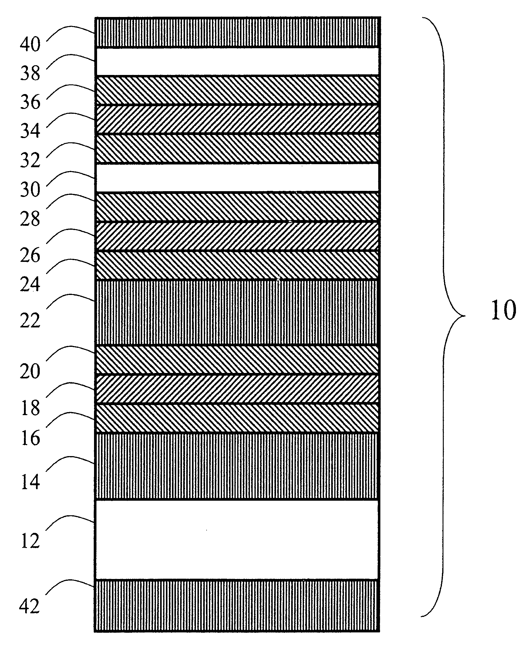
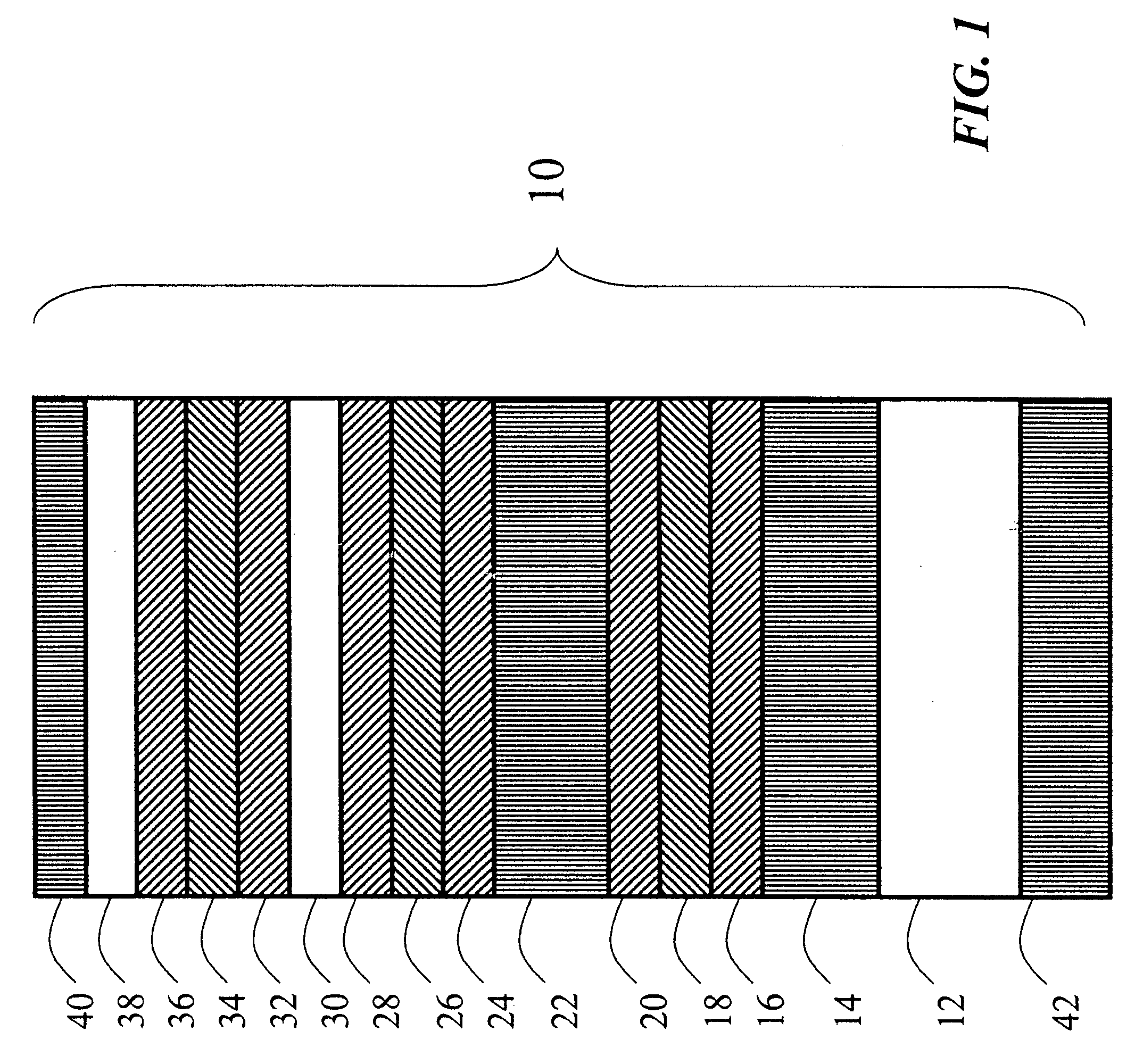
Image

Examples
example i
Dye 6
a. Preparation of 3′-chloro-6′-(4-fluoro-2-methylanilino)fluoran
[0115]To a solution of 3′,6′-dichlorofluoran (1107 g, 3.00 mol) in sulfolane (6 L) was added with stirring anhydrous aluminum chloride (1600 g, 12.00 mol) at such a rate that the temperature of the batch did not exceed 100° C. Upon completion of the addition the reaction mixture was agitated with passive cooling until the temperature reached 85° C., at which point 4-fluoro-2-methylaniline (412.96 g, 3.3 mol) was added dropwise over 15 minutes, with the reaction being maintained at 85° C. by gentle heating. When this addition was complete, 2,6-lutidine (706.2 g, 6.60 mol) was added dropwise over the course of one hour, again maintaining the temperature at 85° C. At this point HPLC indicated that the starting dichlorofluoran had been consumed, so the reaction mixture was quenched into ice-water (40 liters) with vigorous stirring that was maintained for 16 hours. The resulting slurry was filtered and the cake washed w...
example ii
Dye 12
Preparation of 3′,6′-bis(4-fluoro-2-methylanilino)fluoran (Dye 12)
[0117]A mixture of 3′,6′-dichlorofluoran (19.45 g, 50 mmol), 4-fluoro-2-methylaniline (25.0 g, 200 mmol), zinc chloride (22 g, 161 mmol), and zinc oxide (6.60 g, 81 mmol) in sulfolane (100 mL) was stirred at 200° C. for three hours, then cooled to 110° C. over 30 min. The reaction mixture was quenched into a mixture of conc. hydrochloric acid (100 mL) and water (300 mL) to give a red precipitate that was collected by filtration, washed with water (150 mL), and suspended in methanol (200 mL). The suspension was heated to 60° C. and to it was added a solution of conc ammonium hydroxide (15 mL) in methanol (20 mL). The solids went completely into solution for a brief time, after which precipitation of the presumed free base form of the dye began. The slurry was stirred with cooling to 20° C. and maintained at that temperature for 12 hours, then filtered. The cake was washed with cold methanol (70 mL) and dried in v...
example iii
Dye 18
a. Preparation of N,N-dipropyl-4-methyl-2-nitrobenzamide
[0118]To a mixture of 4-methyl-3-nitrobenzoic acid (36.23 g, 0.2 mmol), N,N-dimethylformamide (5 mL), and toluene (85 mL) was added with stirring thionyl chloride (30 mL, 48.8 g, 0.41 mole). The mixture was stirred at gentle reflux for four hours, then distilled to approximately half the volume (67.77 g residual net weight) to remove excess thionyl chloride. This solution was cooled to 20° C., and 22.6 grams of it (nominally 6.67 mmol) was added to a solution of N,N-di-n-propylamine (22.0 g, 0.22 mole) in ethyl acetate (100 mL) resulting in immediate formation of a slurry that was stirred at ambient temperature overnight. This was then quenched into water (150 mL). The organic layer was washed with cold 0.5 N hydrochloric acid (100 mL), then with 5% aqueous sodium bicarbonate, dried (MgSO4) and evaporated to give a colorless oil weighing 16.55 g (94.0%). This was characterized by proton and carbon nmr, as well as electros...
PUM
| Property | Measurement | Unit |
|---|---|---|
| glass transition temperature | aaaaa | aaaaa |
| wavelengths | aaaaa | aaaaa |
| wavelengths | aaaaa | aaaaa |
Abstract
Description
Claims
Application Information