Supercharge Your Innovation With Domain-Expert AI Agents!

Clock dithering process for reducing electromagnetic interference in d/a converters and apparatus for carrying out such process

a clock signal and electromagnetic interference technology, applied in the field of clock signal dithering process and apparatus for carrying out such process, can solve the problems of increasing the complexity of the dithering process, increasing the risk of worsening the linearity performance and dynamic range of the system, and the modulation of the clock signal is likely to worsen the signal quality, so as to achieve greater simplicity and cost-effectiveness, the effect of high performan

Active Publication Date: 2009-06-04
STMICROELECTRONICS SRL
View PDF13 Cites 28 Cited by
  • Summary
  • Abstract
  • Description
  • Claims
  • Application Information

AI Technical Summary

Benefits of technology

[0016]Therefore, the disclosed embodiments provide a clock dithering process and apparatus that can be used in a signal processing chain for high performance D / A conversion. Furthermore, the disclosed embodiments provide a clock dithering process and apparatus of greater simplicity and cost-effectiveness than in prior devices due to its full monolithic integration and to the lack of audio signal degradation.

Problems solved by technology

In audio D / A converters, particularly those D / A converters whose power output is designed to drive loudspeakers, the dithering process would initially seem to require a considerable increase of circuit complexity with the additional risk of worsening the linearity performance and dynamic range of the system, which has to be very high in audio converters.
Nevertheless, increased difficulties occur if the clock signal of a D / A converter comes from an input clock signal through a Phase Locked Loop (PLL) because, when the input signal to the D / A converter is an audio signal, modulation of the clock signal is likely to worsen signal quality, due to intrinsic jitter caused by dithering.
Such time offset causes distortion of the reconstructed signal, which leads to obvious imaginable consequences in terms of quality of the signal transmitted to the loudspeakers.

Method used


Image

  • Clock dithering process for reducing electromagnetic interference in d/a converters and apparatus for carrying out such process
  • Clock dithering process for reducing electromagnetic interference in d/a converters and apparatus for carrying out such process
  • Clock dithering process for reducing electromagnetic interference in d/a converters and apparatus for carrying out such process

Examples


Embodiment Construction

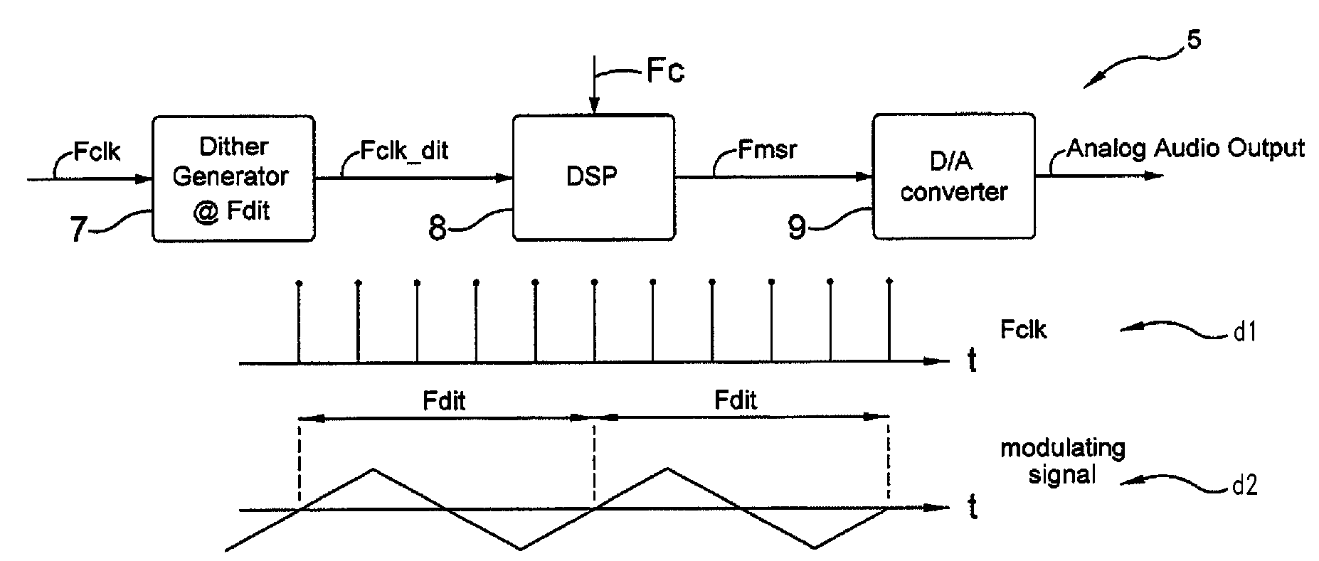
[0034]Referring to FIGS. 4a and 4b, there are shown in FIG. 4a a block diagram of a first embodiment of an apparatus 5 and in FIG. 4b a plurality of diagrams d1-d5 relating to the process carried out with the above apparatus 5 of FIG. 4a, respectively.

[0035]Particularly, the apparatus 5 is configured for receiving an audio bit stream and generating an Analog Audio Output signal whose frequency varies according to a preset modulation scheme.

[0036]For this purpose, the apparatus 5 has a processing chain that includes a dither generator 7, a DSP 8, and a digital-to-analog D / A converter 9.

[0037]Particularly, the dither generator 7 is designed to receive a first input signal Fclk representative of the clock frequency of the apparatus 5 and for generating, according to said modulation scheme, a dithered output signal Fclk_dit, the latter being representative of the dithered version of the first signal Fclk.

[0038]The first signal Fclk, whose graphical representation d1 is shown in FIG. 4b,...


PUM


Abstract

A process and apparatus for generating an output signal whose frequency varies according to a modulation scheme, the process including the steps of providing a dither generator for receiving a first input signal representative of a clock frequency and for generating, according to the modulation scheme, a dithered output signal representative of the first signal at a dithered frequency; providing a DSP for receiving the following input signals: the signal at the dithered frequency and a second signal representative of a clock frequency, the DSP adapted to generate a processed output signal representative of the maximum frequency of the second signal; wherein the modulation scheme has a periodic ultrasonic modulating wave.

Description

BACKGROUND[0001]1. Technical Field[0002]The present disclosure relates to a clock dithering process and apparatus for reducing electromagnetic interference in D / A converters, particularly audio D / A converters.[0003]2. Description of the Related Art[0004]The standards for radio-frequency interference in electronic apparatus have become increasingly stringent, especially in the automotive field, such as a radio, CD player or other audio or audio-visual device.[0005]For example, according to such standards, the spectrum of a signal picked up by an antenna that has a specially regulated position relative to an apparatus undergoing an electromagnetic interference test, is below a preset threshold 1, e.g., a threshold having the profile as shown in FIG. 1.[0006]On the other hand, the diagram of FIG. 2 shows a case in which the apparatus under test emits radiation above the preset threshold 1, which is picked up by the antenna. Due to noise, the antenna might pick up a plurality of peaks 2...

Claims


Application Information

Patent Timeline
IPC IPC(8): H03M1/66
CPCH03L7/0805H03L7/0995H03M1/66H03M1/0656H03L7/18
Inventor ADDUCI, PIETRO MARIOBOTTI, EDOARDOGONANO, GIOVANNI
Owner STMICROELECTRONICS SRL
Features
  • R&D
  • Intellectual Property
  • Life Sciences
  • Materials
  • Tech Scout
  • Unparalleled Data Quality
  • Higher Quality Content
  • 60% Fewer Hallucinations
Learn More