Harmonic suppression mixer and tuner

a mixer and harmonic suppression technology, applied in the field of radio frequency mixers, can solve the problems of unsuitable use for downconverting an rf or if signal to a complex baseband signal, interference into the tuned channel, undesirable harmonic conversion gain, etc., to achieve good harmonic suppression, less harmonic suppression, and prevent interference

Inactive Publication Date: 2009-06-04
SHAH PETER
View PDF11 Cites 66 Cited by
  • Summary
  • Abstract
  • Description
  • Claims
  • Application Information

AI Technical Summary

Benefits of technology

[0016]In one embodiment, at low tuning frequencies, an 8-mixer configuration can be used to achieve good suppression of harmonic signals that are within the occupied band of TV signals to prevent interference from higher channels into the lower channels. At higher tuning frequencies, either the harmonics are outside the active band of television (TV) signals or the harmonics can be suppressed by filtering in the tuner. Therefore, less harmonic suppression is needed in the mixer, and a 4 mixer or 2 mixer configuration can be used, which reduces the required frequency of the LO generator clock signals.

Problems solved by technology

The harmonic conversion gain is undesirable in broadband systems such as TV because interfering signals could reside at frequencies that are converted by the LO harmonics to the output frequency of the channel of interest.
The harmonic interferers could be other TV channels, resulting in interference into the tuned channel.
This mixer architecture configured is suitable for up-conversion in a transmitter, but is not suitable for use to down convert an RF or IF signal to a complex baseband signal.

Method used


Image

  • Harmonic suppression mixer and tuner
  • Harmonic suppression mixer and tuner
  • Harmonic suppression mixer and tuner

Examples


Embodiment Construction

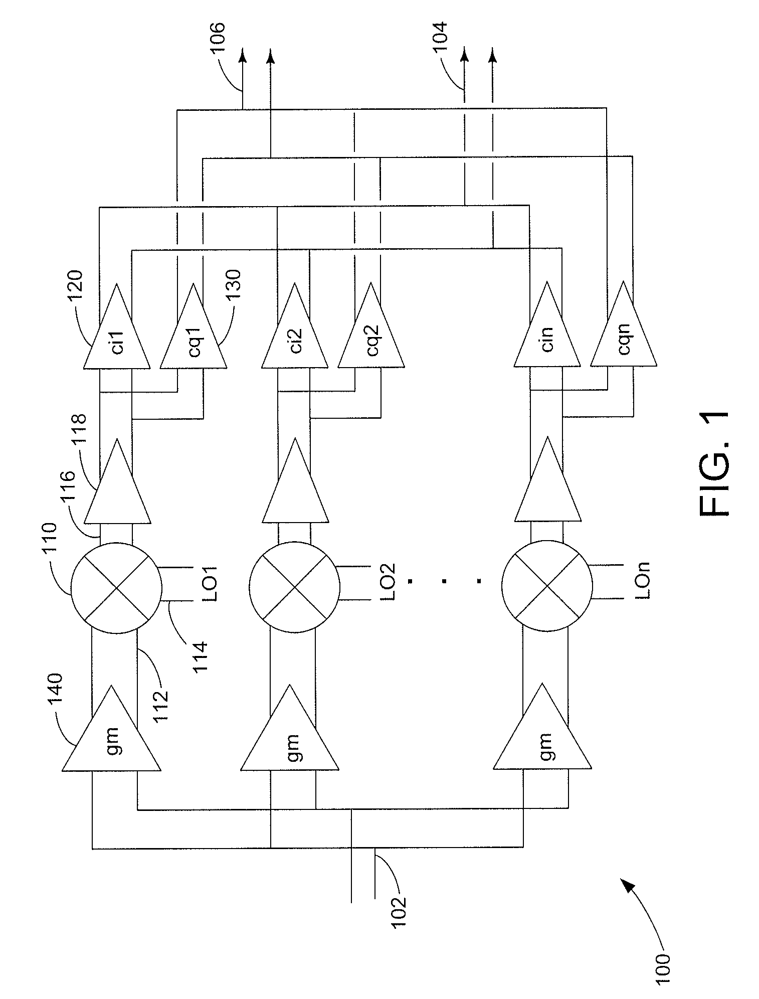
[0040]FIG. 1 shows a harmonic suppression mixer 100. The harmonic suppression mixer 100 has a common input signal 102 that drives transconductance amplifiers 140 to provide signal isolation between each switching mixer 110. The transconductance amplifier 140 prevents the LO signal leaking at switching mixer 110 input from coupling to other mixers and to common input 102. LO signal leakage back to the common input tends to cancel each other due to LO phasing, thus amplifier 140 is optional. Transconductance amplifier 140 can be any type of amplifier depending on the signal type required at the input and output and each can have a different gain. Harmonic mixer 100 comprises multiple switching mixers 110, each with signal input 112, local oscillator (LO) input 114, and signal output 116. All signals are differential drive and can be Gilbert cell or other mixer topologies that are known. A bank of mixers is shown, for example comprising 8 mixers. LO signal 114 is driven by an LO genera...


PUM


Abstract

A harmonic suppression mixer for down converting an RF signal to a complex I and Q baseband signal that uses a plurality of switching mixers each with a gain stage to produce a sinusoidal weighted sum of the mixer outputs. Odd harmonics output by each switching mixer is suppressed in the composite signal. A low skew local oscillator (LO) clock generator creates multiple LO phases and drives the mixers. The mixer can be used in low noise direct conversion RF tuners. The mixer is configurable by programming gain stage coefficient values to achieve a variable number of effective mixers used in combination. At low tuning frequencies, all available mixers are programmed with unique coefficients and driven by different LO clock phases to achieve maximum harmonic suppression. At high tuning frequencies, some mixers are paralleled and duplicate coefficients are programmed or mixers are disabled to reduce the number of effective mixers.

Description

RELATED APPLICATIONS[0001]This application claims priority from U.S. provisional application No. 60 / 552,864 filed Mar. 12, 2004 entitled “Harmonic suppression mixer and tuner”. This application claims priority from U.S. provisional application No. 60 / 636,584 filed Dec. 16, 2004 entitled “Phase-accurate multi-phase wide-band Radio Frequency Local Oscillator generator”.[0002]This application claims priority from U.S. application Ser. No. 11 / 078,050 filed Mar. 11, 2005 entitled “Harmonic Suppression Mixer and Tuner”.FIELD[0003]This disclosure relates to radio frequency mixers and particularly to mixers for suppressing harmonic conversion signals used in radio frequency tuners.BACKGROUND[0004]In radio frequency (RF) applications, it is common for a local oscillator (LO) input signal and a second input signal to be coupled to a mixer to generate an output signal. The output signal is a frequency translation of the second input signal. This process is generally called “up-conversion” or “...

Claims


Application Information

Patent Timeline
Patent Type & Authority Applications(United States)
IPC IPC(8): H04B1/04H04B1/18H03D7/14H04B1/10H04B1/26H04B1/28
CPCH03D7/14H04B1/28H03D2200/0086
Inventor SHAH, PETER
Owner SHAH PETER
Why Eureka
Try Eureka