Calibration circuit of on-die termination device

Active Publication Date: 2009-06-11
SK HYNIX INC
View PDF9 Cites 21 Cited by
  • Summary
  • Abstract
  • Description
  • Claims
  • Application Information

AI Technical Summary

Benefits of technology

[0023]Embodiments of the present invention are directed to providing a calibration circuit of an on-die termination (ODT) device capable of satisfying a system requirement for a constant current by maintaining the amount of current flowing through an input/output node constant even through a power supply voltage fluctuates.
[0024]In accordance with an aspect of the invention, there is provided a code generating

Problems solved by technology

However, such a trend that the swing width of the signal gradually becomes small, influences external noise, and further, a signal reflection caused by impedance mismatch in an interface terminal becomes critical.
Such impedance mismatch is generally caused by external noise, variation of power supply voltage, change in operat

Method used


Image

  • Calibration circuit of on-die termination device
  • Calibration circuit of on-die termination device
  • Calibration circuit of on-die termination device

Examples


Embodiment Construction

[0031]Hereinafter, a calibration circuit of an on-die termination (ODT) device in accordance with the present invention will be described in detail with reference to the accompanying drawings.

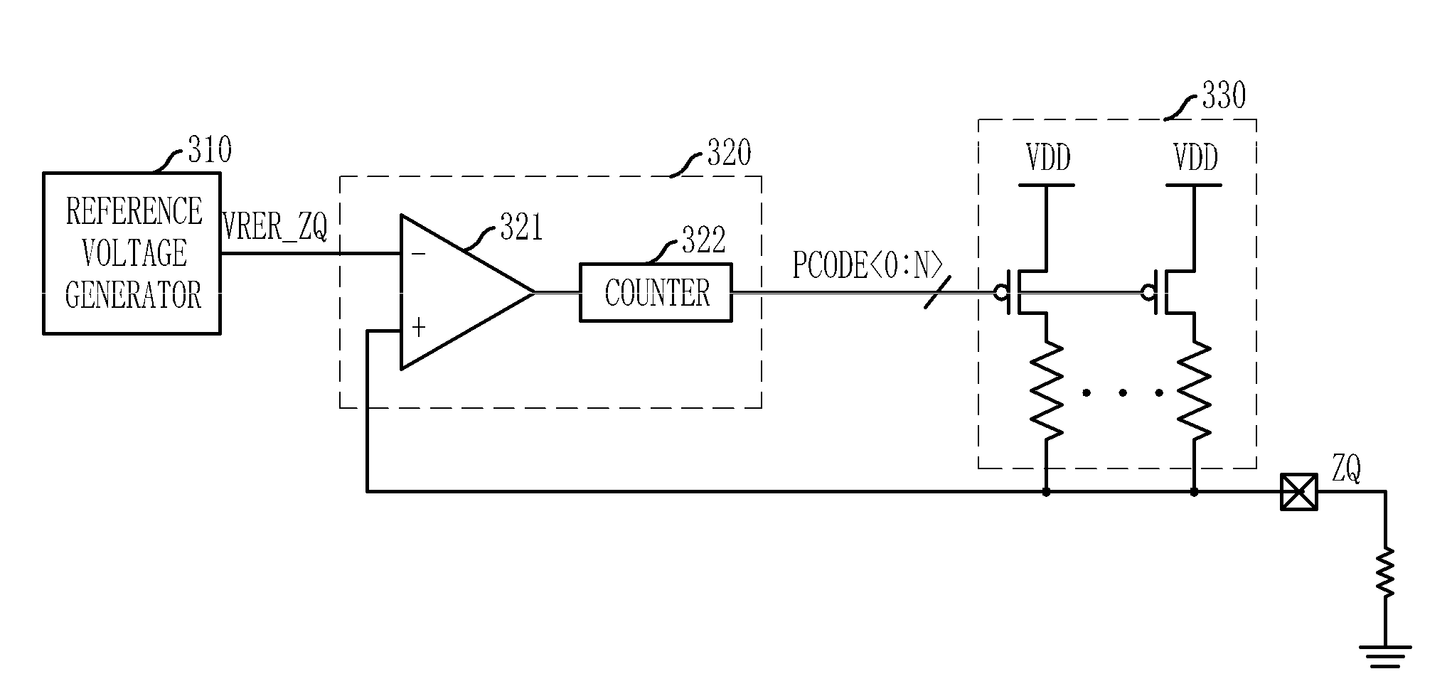
[0032]FIG. 3 is a block diagram of a calibration circuit of an ODT device generating only one kind of calibration codes in accordance with an embodiment of the invention.

[0033]Referring to FIG. 3, the calibration circuit in accordance with the embodiment of the invention includes a code generating unit 320 and a calibration resistor unit 330. The code generating unit 320 receives a voltage of a calibration node ZQ connected to an external resistor 301 and a reference voltage VREF to thereby generate pull-up calibration codes PCODE0:N>. The calibration resistor unit 330 pulls up the calibration node ZQ in response to the pull-up calibration codes PCODE0:N>, and is calibrated such that its resistance becomes higher as a power supply voltage VDD increases. A reference voltage generator 310 configu...


PUM


Abstract

A calibration circuit of an on-die termination device includes a code generating unit configured to receive a voltage of a calibration node connected to an external resistor and a reference voltage to generate pull-up calibration codes. The calibration circuit also includes a pull-up calibration resistor unit configured to pull up the calibration node in response to the pull-up calibration codes. The pull-up calibration resistor unit is calibrated such that its resistance becomes higher as a power supply voltage increases.

Description

CROSS-REFERENCE TO RELATED APPLICATIONS[0001]The present invention claims priority of Korean patent application number 10-2007-0128237, filed on Dec. 11, 2007, which is incorporated by reference in its entirety.BACKGROUND OF THE INVENTION[0002]The present invention relates to a calibration circuit of an on-die termination (ODT) device used for impedance matching at input / output terminals in semiconductor memory devices, and more particularly, to a technology of constantly maintaining the amount of current at input / output terminals in spite of a fluctuation in a power supply voltage.[0003]Semiconductor devices are implemented into integrated circuit (IC) chips such as central processing units (CPUs), memories, and gate arrays, and are incorporated into a variety of electrical products such as personal computers, servers and workstations. Most semiconductor devices include a receiving circuit configured to receive signals from the outside via input pads and an output circuit configure...

Claims


Application Information

Patent Timeline
IPC IPC(8): H03K17/16G01R35/00
CPCH03K19/0005G11C7/10
Inventor KIM, KI-HOBYEON, SANG-JIN
Owner SK HYNIX INC
Why Eureka
Try Eureka