
Guided waves for nondestructive testing of pipes

a pipeline and waveguide technology, applied in the direction of mechanical measurement arrangement, mechanical roughness/irregularity measurement, instruments, etc., can solve the problem that mfl methods can potentially miss crack-like defects, have a large tolerance and low certainty of sizing metal-loss defects

Active Publication Date: 2009-06-11
FUKUOKA BROADCASTING CORPORATION
View PDF8 Cites 86 Cited by
  • Summary
  • Abstract
  • Description
  • Claims
  • Application Information

AI Technical Summary

Benefits of technology

[0009]It is therefore an objective of an aspect of the invention to provide a reliable method and apparatus for detecting coating disbonds using a multi-feature algorithm.
[0010]It is also an objective of an aspect of the invention to provide a more accurate and reliable method for crack and corrosion sizing than is presently available through the employment of guided-wave focusing in real-time, synthetically, and / or geometrically and through the employment of pattern recognition approaches.
[0012]It is also an objective of an aspect of the invention to provide disbond detection capabilities for a range of coating types and thicknesses without being confounded by moderate wall thinning, diametral variations, and wetted / soiled interfaces.
[0026]Additionally, in an example embodiment, correction of the time-delay and amplitude weights may be made to account for the motion of the ILI tool. Corrections are based on the velocity of the tool relative to the desired focal point, wherein the altered path length can be used to adjust the time-delays and amplitude weights. This correction may not be required but may result in enhanced focusing results.

Problems solved by technology

Once a coating is compromised, it is only a matter of time before corrosion begins.
Because the MFL ILI method depends on the ferrous nature of the material being inspected, it is only capable of detecting the effect of the corrosion problem and not the cause; a failure of the protective coating.
Furthermore, MFL methods can potentially miss crack-like defects and have a large tolerance and low certainty for sizing metal-loss defects, such as corrosion.

Method used


Image

  • Guided waves for nondestructive testing of pipes
  • Guided waves for nondestructive testing of pipes
  • Guided waves for nondestructive testing of pipes

Examples


Embodiment Construction

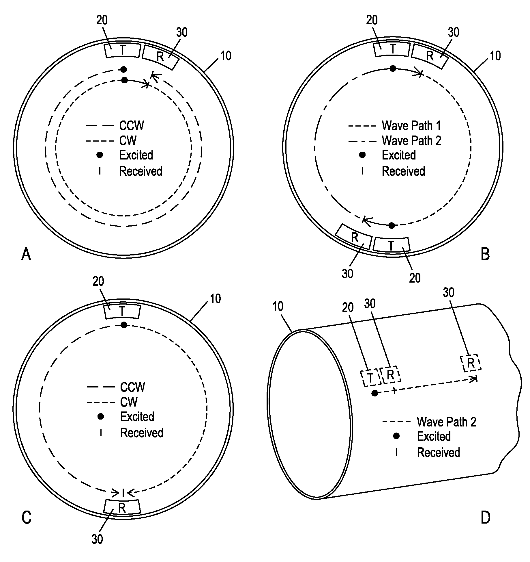
[0039]Referring to FIGS. 3A, 3B, 3C and 3D, in an example embodiment of the invention, an apparatus for implementing a method is developed for the inspection of a coated pipe 10 in which a transmitting sensor 20 and a receiving sensor 30 are separated by some short fixed distance. Referring to FIGS. 4A, 4B, 4C and 4D, all signal features used for disbond detection are calibrated to a reference pulse 40 that travels directly from the transmitter 20 to the receiver 30. The pulse 50, seen in FIGS. 4B-4D, that arrives prior to the reference pulse 40 is electronic noise generated by the electromagnetic acoustic transducers (EMATs) used for excitation and reception. In an example embodiment, there is no specific requirement for the use of EMATs; any device that generates the desired guided-wave mode and frequency is applicable. Several coating disbond detection features are illustrated in the conceptual waveform shown in FIG. 4A. The time-of-flight (“TOF”) 110 and amplitude disparity (“ΔA...


PUM


Abstract

A method for the nondestructive testing of pipeline, and internal or external coatings, using guided ultrasonic waves excited from the inside or outside diameter, wherein at least two transducers are employed to send and receive ultrasound, wherein a data normalization scheme is employed to account for transducer variability, and wherein the hardware arrangement has a number of pulser channels and a number of receiver channels for the collection and storage of signals.

Description

CROSS REFERENCE TO RELATED APPLICATIONS[0001]The present application claims priority under 35 U.S.C. §119(e) to U.S. Provisional Patent Application 60 / 987,864 filed on Nov. 14, 2007, the entirety of which is incorporated by reference herein.FIELD OF THE INVENTION[0002]Aspects of the invention relate to pipeline inspection. More specifically, aspects of the invention relate to providing a guided wave pipeline inspection system and method with enhanced coating disbond detection, corrosion detection and crack sizing capabilities.BACKGROUND INFORMATION[0003]Corrosion is one of the primary preventable causes of failure in transmission pipelines. Protective coatings serve as the first barrier against this phenomenon. Once a coating is compromised, it is only a matter of time before corrosion begins.[0004]The Magnetic-Flux Leakage (MFL) method is currently the dominant technology for the in-line inspection (ILI) of transmission pipeline. Because the MFL ILI method depends on the ferrous na...

Claims


Application Information

Patent Timeline
IPC IPC(8): G01N29/04G06F19/00
CPCG01N29/07G01N29/2462G01N2291/2636G01N2291/106G01N29/341
Inventor VAN VELSOR, JASON K.OWENS, STEVEN E.ROSE, JOSEPH L.
Owner FUKUOKA BROADCASTING CORPORATION
Learn More