Micro gas sensor and manufacturing method thereof

Active Publication Date: 2009-06-18
ELECTRONICS & TELECOMM RES INST
View PDF12 Cites 62 Cited by
  • Summary
  • Abstract
  • Description
  • Claims
  • Application Information

AI Technical Summary

Benefits of technology

[0019]Therefore, the present invention provides a micro gas sensor which has low power consumption, durability against mechanical or thermal impacts, includes a gas sensing film that is formed by using various types of material such as metal oxide, metal, semiconductors, polymer, nano-materials, and the like and has a rapid heating and cooling time, has an improved output corresponding to changes in a gas concentration, that is, an improved sensitivity, and can be mass-produced at low cost.

Problems solved by technology

The performed silicon wet etching in the manufacturing processes is simple, however, there are problems in that a depth and a shape of the cavity cannot be precisely controlled and since a device die is relatively large, manufacturing cost is high.
In addition, a supporting layer has a suspended structure using only the insulating layer, so that the micro gas sensor is vulnerable to repeated thermal or mechanical impacts.
Particularly, although the SiC heater is used to improve temperature characteristics, the SiC is formed by performing a special deposition process using high temperature, so that there is a problem of compatibility with a standard semiconductor manufacturing process.
The structure has problems in that since the wet etching is used, a depth or a shape of the groove cannot be controlled and durability is low.

Method used


Image

  • Micro gas sensor and manufacturing method thereof
  • Micro gas sensor and manufacturing method thereof
  • Micro gas sensor and manufacturing method thereof

Examples


Embodiment Construction

[0051]Exemplary embodiments of the present invention will now be described in detail with reference to the accompanying drawings.

[0052]In the description, the detailed descriptions of well-known functions and structures may be omitted so as not to hinder the understanding of the present invention.

[0053]In the drawings, lengths and sizes of layers and regions may be exaggerated for clarity. In addition, it will be understood that when an element or layer is referred to as being “on” another element or layer, the element or layer can be directly on another element or layer or intervening elements or layers.

[0054]Like reference numerals designate like elements throughout the specification.

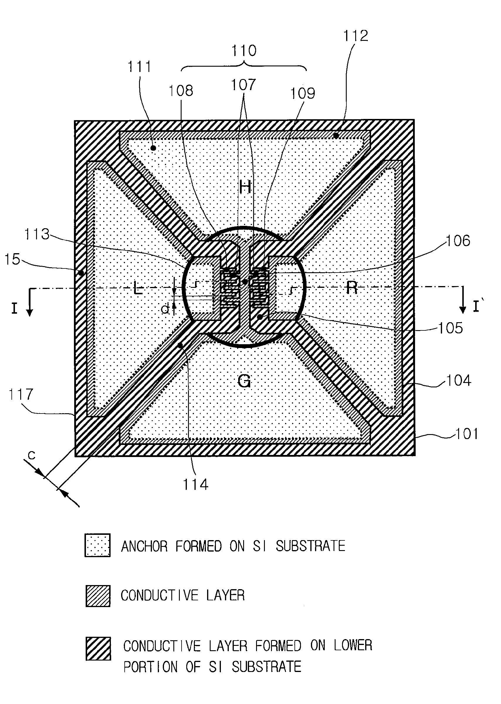
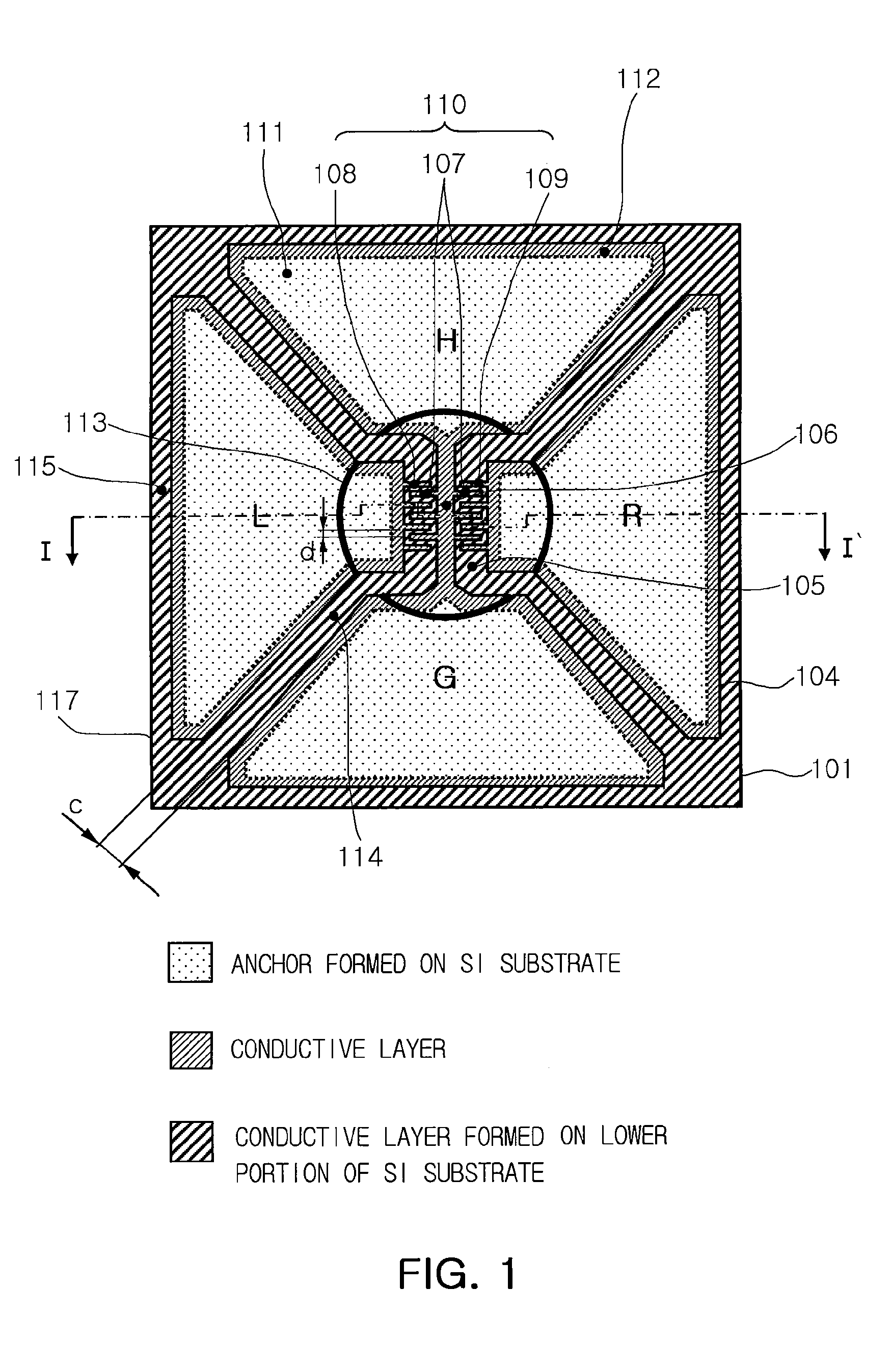
[0055]FIG. 1 is a top plan view illustrating a micro gas sensor having four electrode pads according to an embodiment of the present invention. FIG. 3 is a cross-sectional view illustrating the micro gas sensor taken along line I-I′ of FIG. 1. The cross-sectional view of FIG. 3 is the same as a cross-...


PUM


Abstract

Provided is a micro gas sensor including: a substrate; an open cavity and electrode pad separation grooves formed on the substrate; a plurality of electrode pads formed on an upper portion of the substrate and electrically insulated from each other by the electrode pad separation grooves; a micro heater connected to a plurality of the electrode pads by a bridge structure and suspended on the open cavity; a plurality of sensing electrodes formed on the same plane between the micro heater and a plurality of the electrode pads in a cantilever array and suspended on the open cavity; and a gas sensing film formed to be hung down between microelectrode finger spacings of a plurality of the sensing electrodes to represent changes in characteristics according to a gas concentration by contacting surfaces of the micro heater and a plurality of the sensing electrodes. Therefore, the micro gas sensor can have low power consumption, a rapid heating and cooling time, high durability, high sensitivity characteristics, and a capability of easily forming a gas sensing film by using various materials. In addition, the micro gas sensor can be miniaturized and mass-produced at low cost in a simple structure using only a single pattern mask.

Description

CROSS-REFERENCE TO RELATED APPLICATIONS[0001]This application claims the priority of Korean Patent Application No. 10-2007-0131984 filed on Dec. 17, 2007, in the Korean Intellectual Property Office, the disclosure of which is incorporated herein by reference.BACKGROUND OF THE INVENTION[0002]1. Field of the Invention[0003]The present invention relates to a micro gas sensor and a method of manufacturing the same for precisely measuring a gas concentration, and more particularly, to a micro gas sensor and a method of manufacturing the same that has low power consumption, a rapid heating and cooling time, high durability, high sensitivity characteristics, a capability of easily forming a gas sensing film by using various materials, and a plurality of suspended sensing electrodes, which can be miniaturized and mass-produced at low cost through a simple manufacturing process using only a single pattern mask.[0004]This work was supported by the IT R&D program of MIC / IITA [2006-S-007-02, Ub...

Claims


Application Information

Patent Timeline
IPC IPC(8): G01N9/00H01L21/00
CPCG01N33/0027G01N27/128B81C1/00G01N27/12
Inventor JUN, CHI HOONKO, SANG CHOONJUNG, MOON YOUNPARK, SEON HEE
Owner ELECTRONICS & TELECOMM RES INST
Why Eureka
Try Eureka