Translucent solar cell and manufacturing method thereof

a solar cell and transparent technology, applied in the direction of sustainable manufacturing/processing, climate sustainability, semiconductor devices, etc., can solve the problems of short circuit between short circuits, short circuits, and increased risk of short circuits, so as to avoid short circuits, reduce manufacturing costs, and avoid insufficient light transmissibility

Inactive Publication Date: 2009-06-18
NEXPOWER TECH
View PDF11 Cites 53 Cited by
  • Summary
  • Abstract
  • Description
  • Claims
  • Application Information

AI Technical Summary

Benefits of technology

[0008]To overcome the shortcomings in the prior art, the present invention provides a translucent solar cell and a manufacturing method thereof. The translucent solar cell comprises, in order of stacking, a substrate, a first electrode layer (also referred to as “front electrode layer”), a photoconductive layer (also referred to as “photoactive layer”) and a second electrode layer (also referred to as “back electrode layer”). A plurality of first light-transmissive apertures are formed on the second electrode layer by removing material thereof, and the plurality of first light-transmissive apertures are further extended in a depth direction into the photoconductive layer to form a plurality of second light-transmissive apertures corresponding to the first light-transmissive apertures, wherein a projected area of each of the second light-transmissive apertures is smaller than that of a corresponding first light-transmissive aperture. Therefore, by removing different areas of material from different film layers, short-circuits can be avoided during the process of forming holes by material removal. In addition, the projected patterns of the light-transmissive apertures may take the shape of a strip, a rectangle, a polygon, a circle, an ellipse, an arc, or any other irregular shapes by using a laser together with a mask, thus making it possible to change the areas and shapes of the removed regions, thereby avoiding insufficient light transmissibility. Furthermore, a higher specification or higher power laser is not required, thus reducing the manufacturing cost.
[0009]Accordingly, it is a primary objective of the present invention to provide a translucent solar cell, wherein projected patterns of light-transmissive apertures can be arbitrarily changed to improve an overall light-transmissibility of the translucent solar cell.
[0010]A secondary objective of the present invention is to provide a translucent solar cell and a manufacturing method thereof, wherein different areas of material can be removed from different film layers during a manufacturing process so as to avoid short-circuit between film layers.
[0011]A further objective of the present invention is to provide a translucent solar cell, wherein light-transmissive apertures of arbitrary shapes can be formed by using a laser together with a mask to reduce manufacturing cost.

Problems solved by technology

In the prior art cited above, while forming the light-transmissive regions, no matter whether a laser or an etching process is used to remove the film material such that holes or scribe lines are formed on the film layer, incomplete removal of film material from the holes or scribe lines can easily occur when the film layer is being cut due to a thermal effect, thus causing bridging of the conductive layers and hence a short-circuit therebetween.
As a result, each time the film material is removed during the process, the risk of having a short-circuit increases.
Furthermore, if a laser is used, variation of the shape and size of the resulting hole is limited due to the limitation of laser beam itself.
If holes of different shapes or of a larger size are desired, a laser with higher specification or higher power is required, thus increasing the manufacturing cost.

Method used


Image

  • Translucent solar cell and manufacturing method thereof
  • Translucent solar cell and manufacturing method thereof
  • Translucent solar cell and manufacturing method thereof

Examples


Embodiment Construction

[0017]The present invention relates to a translucent solar cell and a manufacturing method thereof. The principle used therein regarding the photoelectric conversion of solar cells has been known to those of ordinary skill in the art and is therefore not described in detail in the following description. Also, it is to be understood that the drawings referred to in the following description are merely structural schematic views showing features of the present invention and are not made according to their actual dimensions.

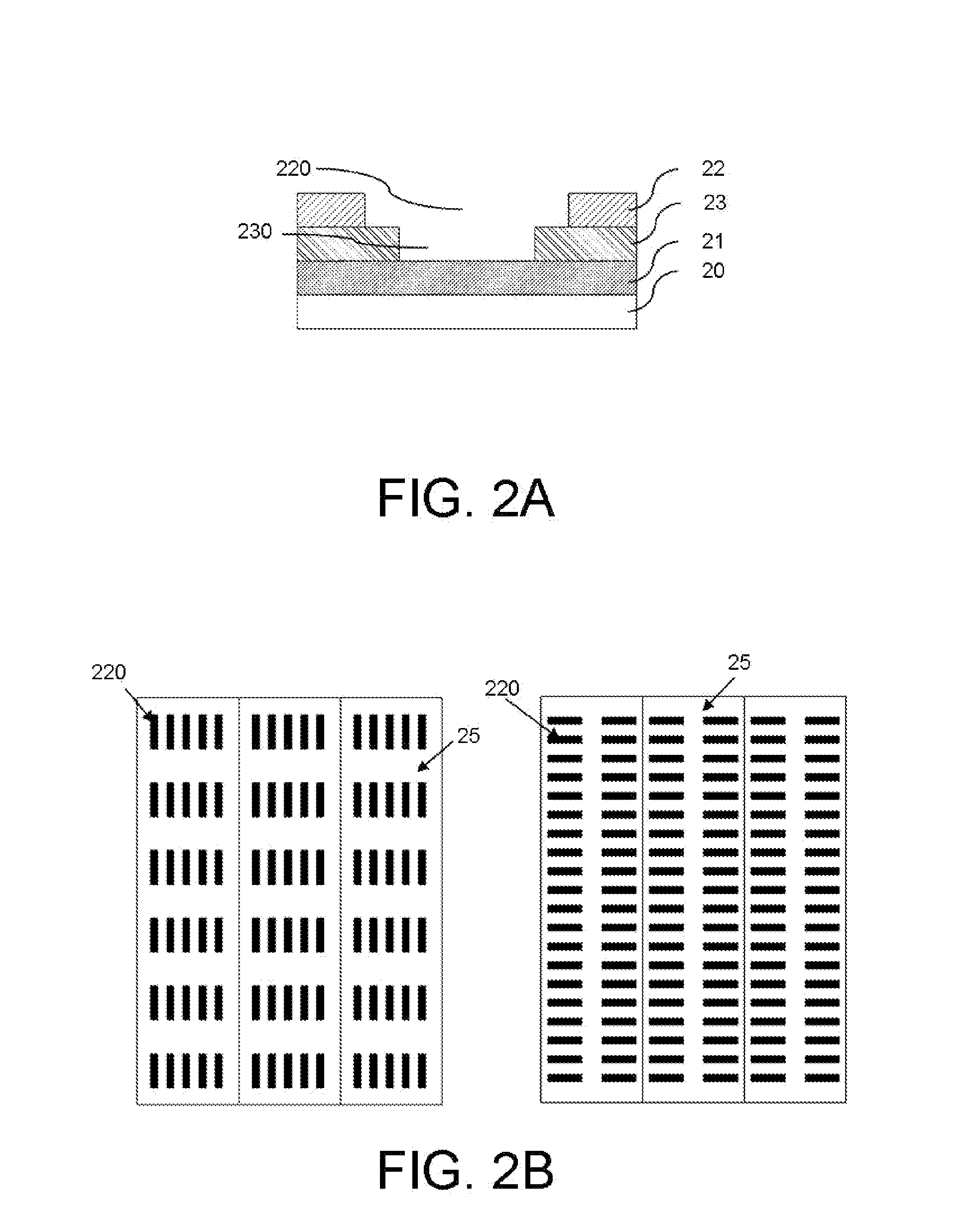
[0018]FIG. 2A illustrates a cross-sectional view of a translucent solar cell in accordance with a first preferred embodiment of the present invention. The translucent solar cell 2 includes, in order of stacking, a substrate 20, a first electrode layer 21, a photoconductive layer 23 and a second electrode layer 22. The first electrode layer 21 is formed on the substrate 20 by a method selected from the group consisting of sputtering, atmospheric pressure chemical vap...


PUM


Abstract

The present invention provides a translucent solar cell and a manufacturing method thereof. The translucent solar cell comprises, in stacking order, a substrate, a first electrode layer, a photoconductive layer and a second electrode layer. The translucent solar cell is characterized in that there are formed a plurality of first light-transmissive apertures on the second electrode layer and the plurality of first light-transmissive apertures are further extended in a depth direction to the photoconductive layer to form a plurality of second light-transmissive apertures corresponding to the first light-transmissive apertures. A projected area of each of the second light-transmissive apertures is equal to or smaller than that of a corresponding first light-transmissive aperture.

Description

BACKGROUND OF THE INVENTION[0001]1. Field of the Invention[0002]The present invention relates to a translucent solar cell and a manufacturing method thereof, and more particularly, to a translucent solar cell which has improved light transmissibility and can avoid short-circuit during a manufacturing process thereof.[0003]2. Description of Related Art[0004]Thin-film solar cells include various thin films deposited on a substrate. These thin films are partitioned by laser-cutting into a number of individual and series-connected unit cells. The thin films deposited on the substrate sequentially includes, in a bottom-up direction, a front electrode layer, a photoconductive layer and a back electrode layer. The front electrode layer can be made of SnO2, ITO, ZnO, AZO, GZO, IZO, etc. The photoconductive layer can be made of IV group semiconductors or III-V, II-VI or I-III-VI group compounds. The back electrode layer can be made of Ag, Al, or Cr.[0005]In general, the front electrode layer...

Claims


Application Information

Patent Timeline
Patent Type & Authority Applications(United States)
IPC IPC(8): H01L31/00
CPCH01L31/186H01L31/0468Y02E10/50Y02P70/50
Inventor LU, CHUN-HSIUNGBI, CHIEN-CHUNG
Owner NEXPOWER TECH
Why Eureka
Try Eureka