Control device of a plurality of switching converters

Active Publication Date: 2009-06-18
STMICROELECTRONICS SRL
View PDF3 Cites 23 Cited by
  • Summary
  • Abstract
  • Description
  • Claims
  • Application Information

AI Technical Summary

Benefits of technology

[0011]In view of the disclosed prior designs, the present disclosure provides a control

Problems solved by technology

Multiple and multiphase approaches are used when with a single converter it is impossible or economically disadvantageous to comply with design specifications.
In this case, the maximum benefit from the use of a multiplicity of converters is derived when the system is called upon to work at full load, whereas with reduced loads to have many converters available leads to redundancy.
Except for some cases in which redundancy is required in the supply system to ensure very high levels of service continuity, in general this constitutes a waste.
Furthermore, at reduced loads, t

Method used


Image

  • Control device of a plurality of switching converters
  • Control device of a plurality of switching converters
  • Control device of a plurality of switching converters

Examples


Example

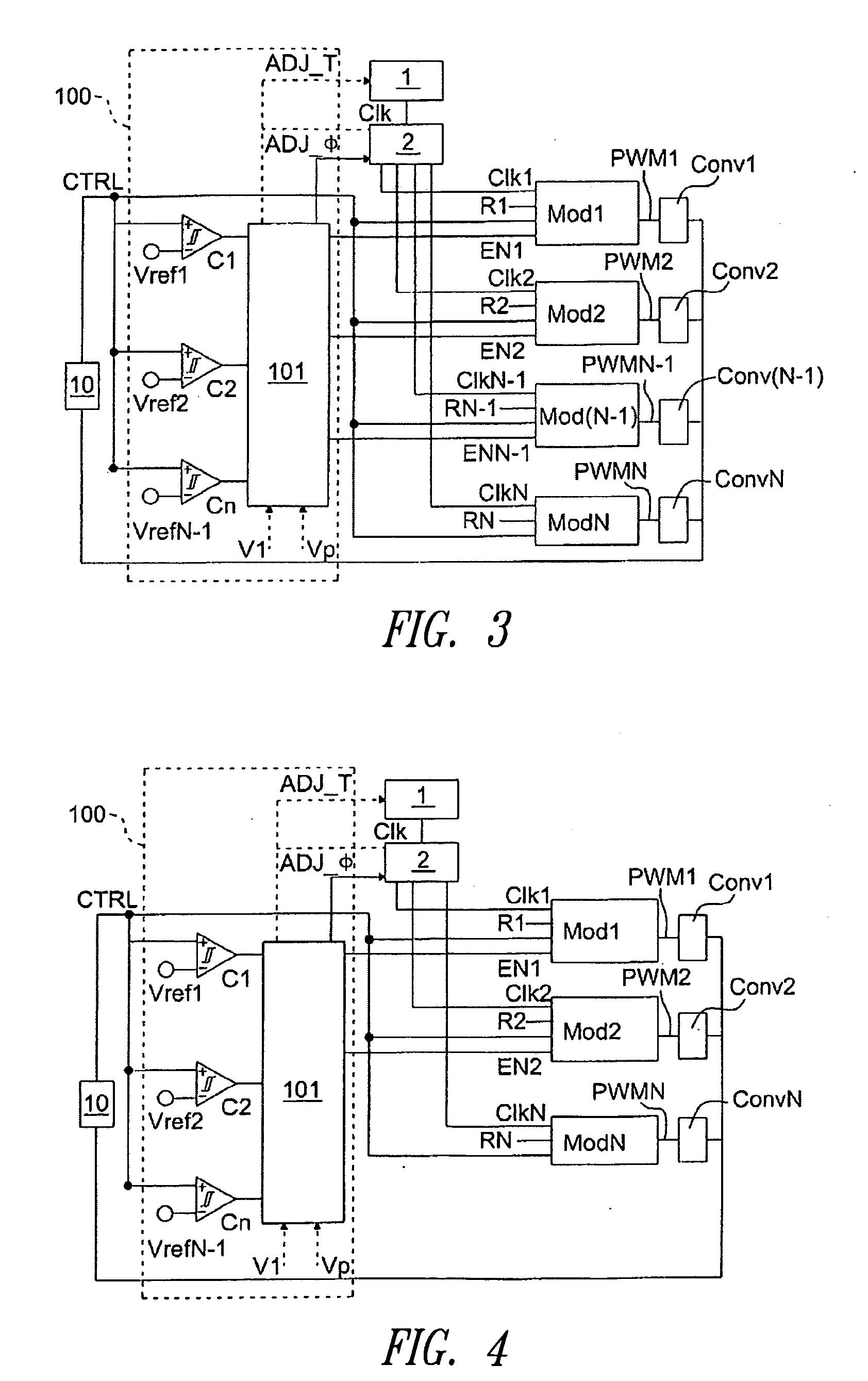
[0057]In FIG. 4 there is shown a control device according to a second embodiment of the present disclosure. The device is useful in the case of PWM modulators of “trailing edge” type, i.e., in which the conduction cycles of the power switch are initiated by the signals Clkj and terminated by the comparison between CTRL and Rj. This differs from the latter substantially through the lack of signals ENj (j=1,2, . . . N−1) and through the fact that the disabling function of the PWM modulators and therefore of the associated converters is entrusted to the block 2. The latter in fact disables the j-th modulator simply by no longer sending the corresponding clock signal Clkj, so that the power switch commanded by it is not switched on.

Example

[0058]In FIG. 5 there is shown a control device according to a third embodiment of the present disclosure in which each PWM modulator communicates with the block 2 with a signal φj (j=1,2, . . . N−1) instead of the line ADJ_φ coming from the device 101. In this case any action on the block 1 is of necessity actuated through the block 2.

[0059]In FIG. 6 there is shown a possible embodiment of the block 10 of FIGS. 2-5 in which the converters are not insulated. The block 10 includes a series of two resistances R1 and R2 arranged between the voltage Vout and ground GND, an error amplifier 300 having a non-inverting input terminal connected to a voltage supply Vref300 and the inverting input terminal connected to the voltage V300=R2*Vout / (R1+R2) and a feedback network 301 arranged between the output and the inverting input terminal of the amplifier 300.

[0060]In FIGS. 7a and 7b there are shown possible embodiments of the block 10 of the FIGS. 2-5 in the case of insulated converters. The v...


PUM


Abstract

A control device of a plurality of switching converters is disclosed; each converter comprises at least one power switch and is associated with a control circuit of the at least one power switch. The control device comprises means suitable for comparing a signal representative of the load of the plurality of converters with a plurality of reference signals and suitable for enabling or disabling at least one of said plurality of control circuits in response to said comparison.

Description

BACKGROUND[0001]1. Technical Field[0002]The present disclosure relates to a control device of a plurality of switching converters.[0003]2. Description of the Related Art[0004]In the prior art, multiple converters are known; they are made by means of a parallel combination of two or more switching converters in any of the standard types (for example, buck, flyback, boost, etc.), typically the same for all, in such a way that they share the same voltage source and dispense power on the same load. If then in such converters control methods are actuated, that fundamentally consist of staggering in an appropriate manner the PWM pulse trains that control each converter, it is more proper to speak of “multiphase” converters.[0005]Multiple and multiphase approaches are used when with a single converter it is impossible or economically disadvantageous to comply with design specifications. The most common situation in which such approaches may be suitable is at a high level of power current. ...

Claims


Application Information

Patent Timeline
IPC IPC(8): H02J1/00
CPCH02J1/102Y02B70/1491H02M2001/0048H02M3/1584Y02B70/10H02M1/0048
Inventor ADRAGNA, CLAUDIOGATTAVARI, GIUSEPPE
Owner STMICROELECTRONICS SRL
Why Eureka
Try Eureka