

Hot melt sealant containing desiccant for use in photovoltaic modules
a technology of photovoltaic modules and desiccant, which is applied in the direction of pv power plants, synthetic resin layered products, chemistry apparatus and processes, etc., can solve the problems affecting the performance of thin film photovoltaic materials, and a long-standing problem of water penetration into solar modules, etc., to achieve the effect of simplifying the manufacturing process associated, facilitating application and prolonging the life of tfpps
- Summary
- Abstract
- Description
- Claims
- Application Information
AI Technical Summary
Benefits of technology
Problems solved by technology
Method used
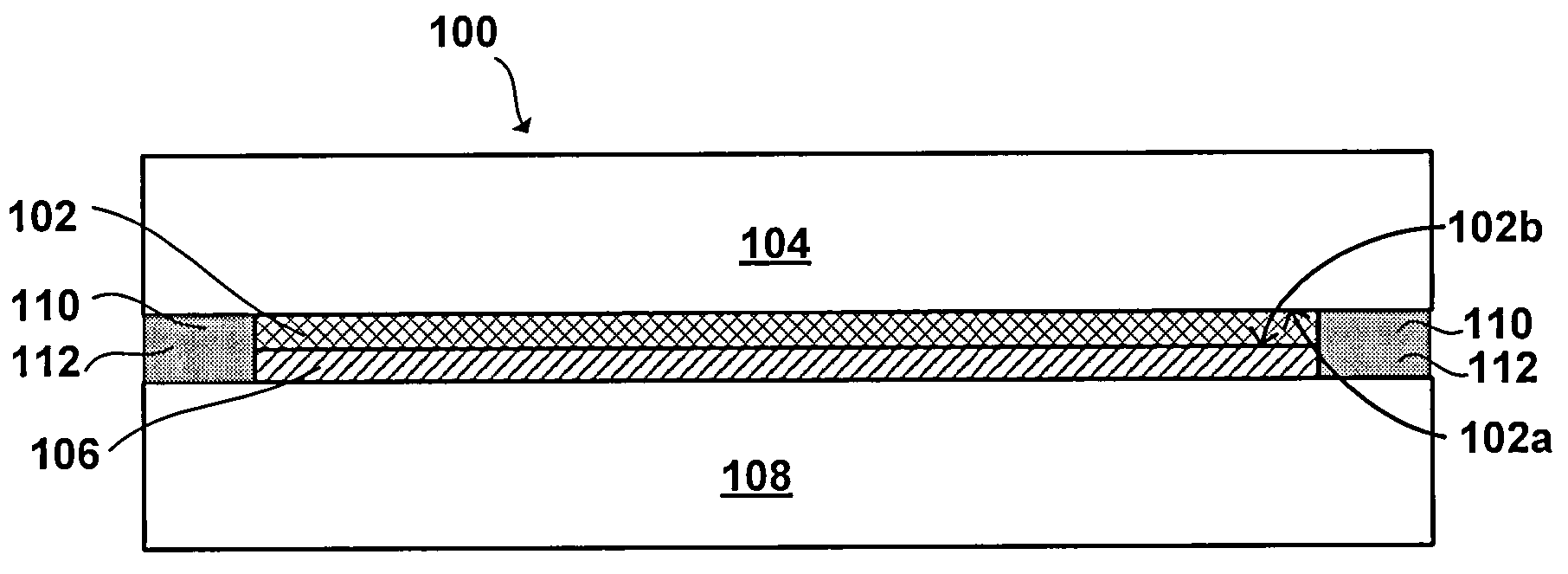
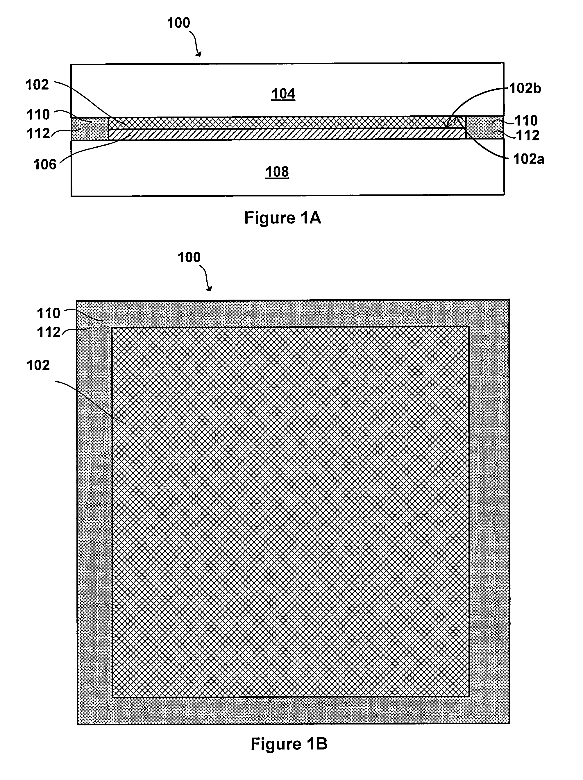
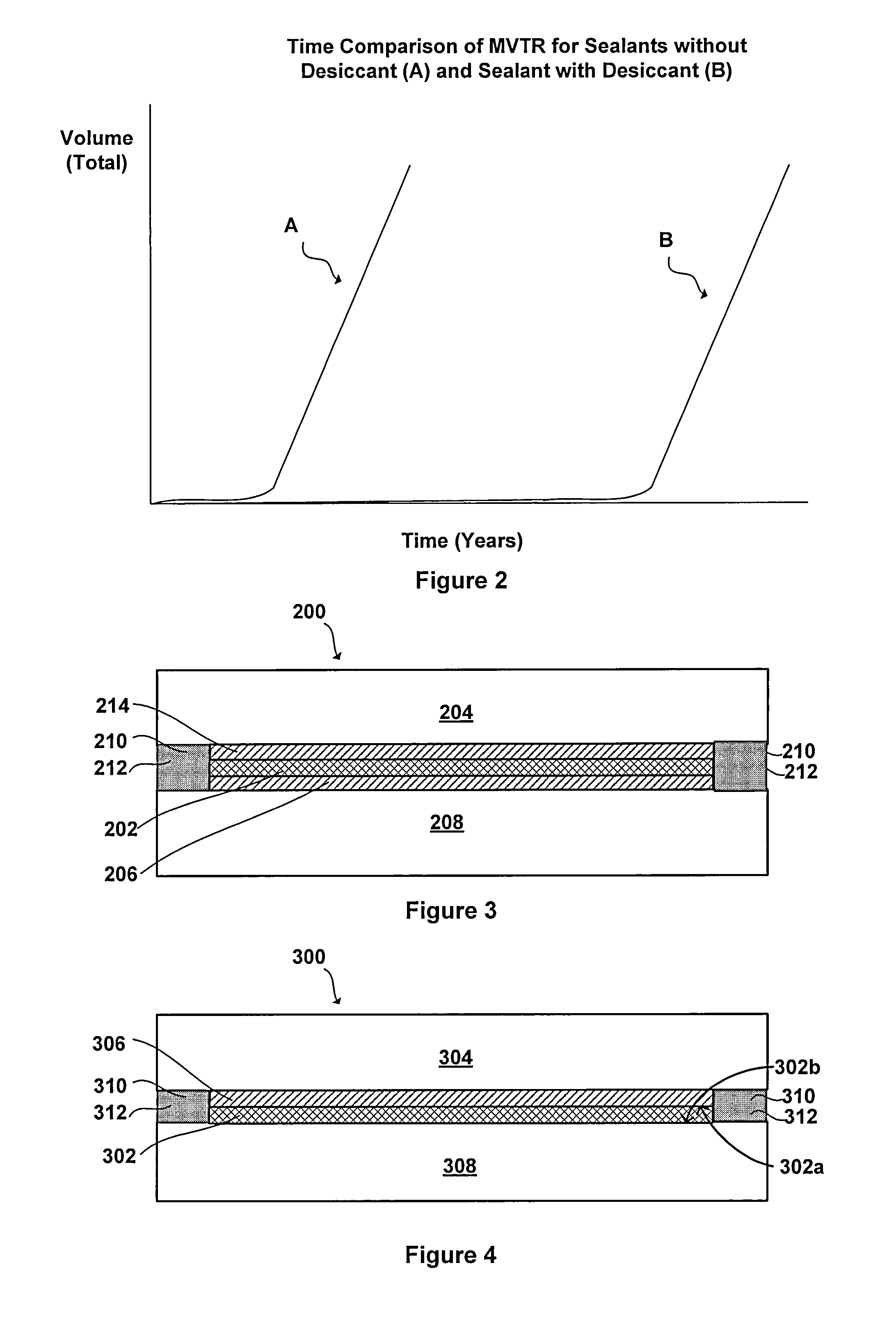
Image

Examples
example 1
[0054 includes a hot-melt sealant comprised of the following chemical composition:
ComponentChemical NameManufacturer% (Total Wt)Butyl 268Butyl rubberExxon10Rextac 2585AmorphousHuntsman40polyalphaolefinH-100 WHydrocarbon ResinEastman10MOLSIVMolecular SieveUOP19Hubercarb Q6Calcium carbonateHuber16Hi-Sil 233Silicon DioxidePPG5%TOTAL100
[0055]In accordance with another exemplary embodiment, Example 2 includes a curing hot-melt sealant comprised of the following chemical composition:
ComponentChemical NameManufacturerPercentB-10 PIBPolyisobutyleneBASF10Rextac 2585Amorphous polyalphaolefinHuntsman30DFDA-5451NTMoisture curing PEDow19DFDA-5481 NTMoisture curing PE catalystDow1H-100 WHydrocarbon ResinEastman10MOLSIVMolecular SieveUOP19Hubercarb Q6Calcium carbonateHuber11TOTAL100
[0056]The sealant compositions of Example 1 and Example 2 may be mixed in a sigma type mixer until homogenous and transferred to a five-gallon bucket that can be placed under a pumping device such as a (e.g., a Graco p...
PUM
| Property | Measurement | Unit |
|---|---|---|
| humidity | aaaaa | aaaaa |
| temperature | aaaaa | aaaaa |
| melt flow time | aaaaa | aaaaa |
Abstract
Description
Claims
Application Information