Thermal electron emission source having carbon nanotubes and method for making the same

a carbon nanotube and electron emission source technology, applied in the manufacture of photo-emissive cathodes, thermionic cathodes, electric discharge tubes, etc., can solve the problems of low electron-emission lifespan, limited quantity of electron-emission alkaline earth metal oxide, and less stable thermal electron emission sources, etc., to achieve stable electron emission characteristics, improve electron-emission efficiency, and prolong the effect of li

Inactive Publication Date: 2009-06-25
HON HAI PRECISION IND CO LTD +1
View PDF18 Cites 13 Cited by
  • Summary
  • Abstract
  • Description
  • Claims
  • Application Information

AI Technical Summary

Benefits of technology

[0009]Compared with the conventional thermal electron emission source, the present thermal electron emission source has the following advantages. Firstly, the carbon nanotube is stable at high temperature, and thus the thermal electron emission source has stable electron emission characteristics. Secondly, the electron emission particles are uniformly dispersed into the carbon nanotube string, providing more electron emission

Problems solved by technology

Therefore, the thermal electron emission source is less stable.
Further, the alkaline earth metal oxide layer is only formed on the surface of the base

Method used


Image

  • Thermal electron emission source having carbon nanotubes and method for making the same
  • Thermal electron emission source having carbon nanotubes and method for making the same
  • Thermal electron emission source having carbon nanotubes and method for making the same

Examples


Embodiment Construction

[0015]The present thermal electron emission source is further described below with reference to the drawings.

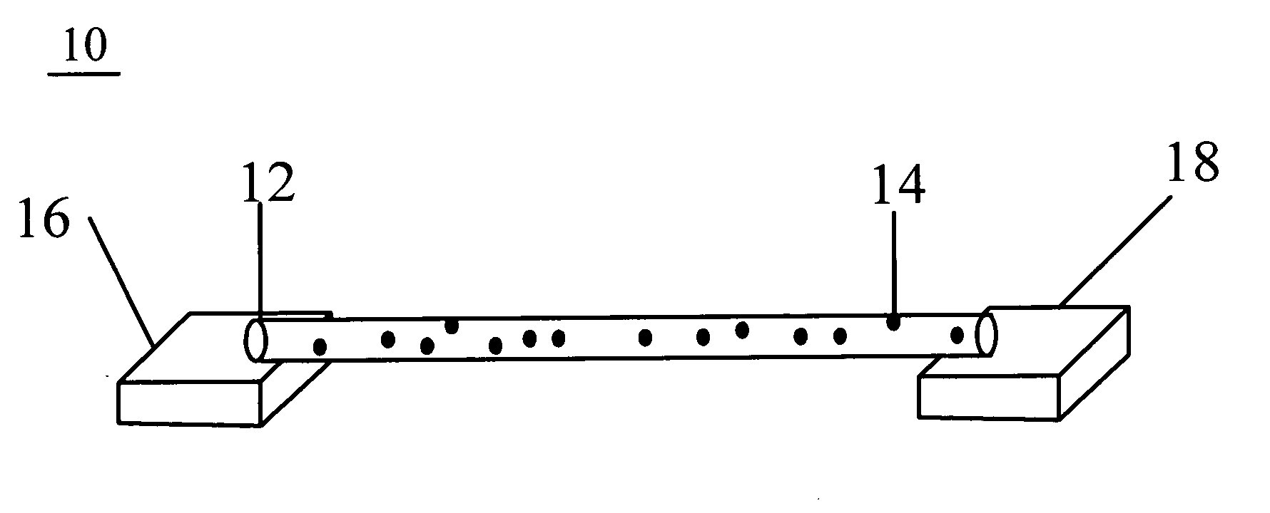
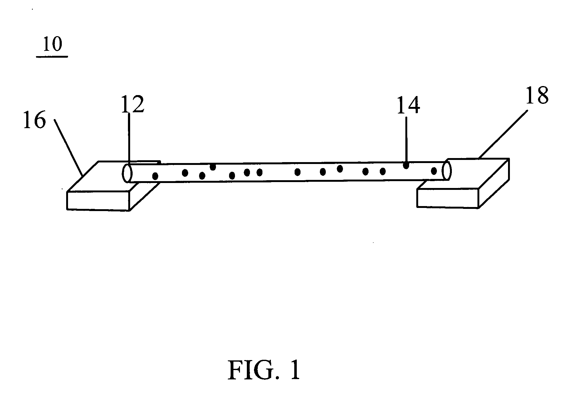
[0016]Referring to FIG. 1, a thermal electron emission source 10 includes a carbon nanotube (CNT) string 12 functioning as a matrix, a number of electron emission particles 14 uniformly dispersed into the CNT string 12, a first electrode 16, and a second electrode 18. Two opposite ends of the CNT string12 are respectively electrically connected to and in contact with the first electrode 16 and the second electrode 18 by a conductive paste / adhesive, such as a silver paste. The first and second electrodes 16 and 18 are separated and insulated from each other and made of a conductive material, such as a metal or alloy.

[0017]The electron emission particles 14 are made of at least one low work function material selected from the group consisting of alkaline earth metal oxides, alkaline earth metal borides, and a mixture thereof. The alkaline earth metal oxides are beneficially mat...


PUM


Abstract

A thermal electron emission source includes a first electrode, a second electrode insulated from the first electrode, a carbon nanotube string electrically connected to and in contact with the first electrode and the second electrode, and a number of electron emission particles. The carbon nanotube string is composed of a number of closely packed carbon nanotube bundles, and each of the carbon nanotube bundles includes a number of carbon nanotubes. The electron emission particles are uniformly dispersed in the carbon nanotube string and are coated on the surfaces of the carbon nanotubes. A method for making the thermal electron emission source is also provided.

Description

RELATED APPLICATIONS[0001]This application is related to commonly-assigned, co-pending application: U.S. patent application Ser. No. 12 / 006,305, entitled “METHOD FOR MANUFACTURING FIELD EMISSION ELECTRON SOURCE HAVING CARBON NANOTUBES”, filed Dec. 29, 2007. The disclosure of the above-identified application is incorporated herein by reference.BACKGROUND[0002]1. Field of the Invention[0003]The present invention relates to thermal electron emission sources and, more particularly, to a thermal electron emission source including carbon nanotubes and a method for making the same.[0004]2. Discussion of Related Art[0005]A thermal electron emission source is a device widely applied in gas lasers, arc-welding, plasma-cutting, electron microscopy, x-ray generators, and the like. The conventional thermal electron emission source is constructed in that a layer of electron emissive alkaline earth metal oxide, such as BaO, SrO, CaO, or a mixture thereof, is formed on a base made of an alloy inclu...

Claims


Application Information

Patent Timeline
IPC IPC(8): H01J1/02H01J9/02
CPCH01J1/14H01J2201/196H01J9/04
Inventor XIAO, LINLIU, PENGLIU, LIANGJIANG, KAI-LIWEI, YANGQIAN, LIFAN, SHOU-SHAN
Owner HON HAI PRECISION IND CO LTD
Why Eureka
Try Eureka