Illuminator, image display apparatus, and polarization conversion/diffusion member

Inactive Publication Date: 2009-06-25
COLUMBIA PEAK VENTURES LLC
View PDF10 Cites 29 Cited by
  • Summary
  • Abstract
  • Description
  • Claims
  • Application Information

AI Technical Summary

Benefits of technology

[0061]The polarization conversion/diffusion member according to the fourth aspect of the invention is configured to have the polarization converter formed on one side of a base, the light diffusion section formed on the other side of the base that is opposite the on

Problems solved by technology

An image having such a speckle pattern disadvantageously gives a viewer a sense of glaring flicker.
In the technologies described in JP-A-6-208089 and JP-A-2005-84117, however, light emitted from the light source is diffused in the diffuser plate to reduce speckle nois

Method used


Image

  • Illuminator, image display apparatus, and polarization conversion/diffusion member
  • Illuminator, image display apparatus, and polarization conversion/diffusion member
  • Illuminator, image display apparatus, and polarization conversion/diffusion member

Examples


first embodiment

[0078]A first embodiment of a projector according to the invention will be described with reference to FIGS. 1 to 5.

[0079]The present embodiment will be described with reference to a projection-type projector that projects color light containing image information produced by a spatial light modulator on a screen through a projection system.

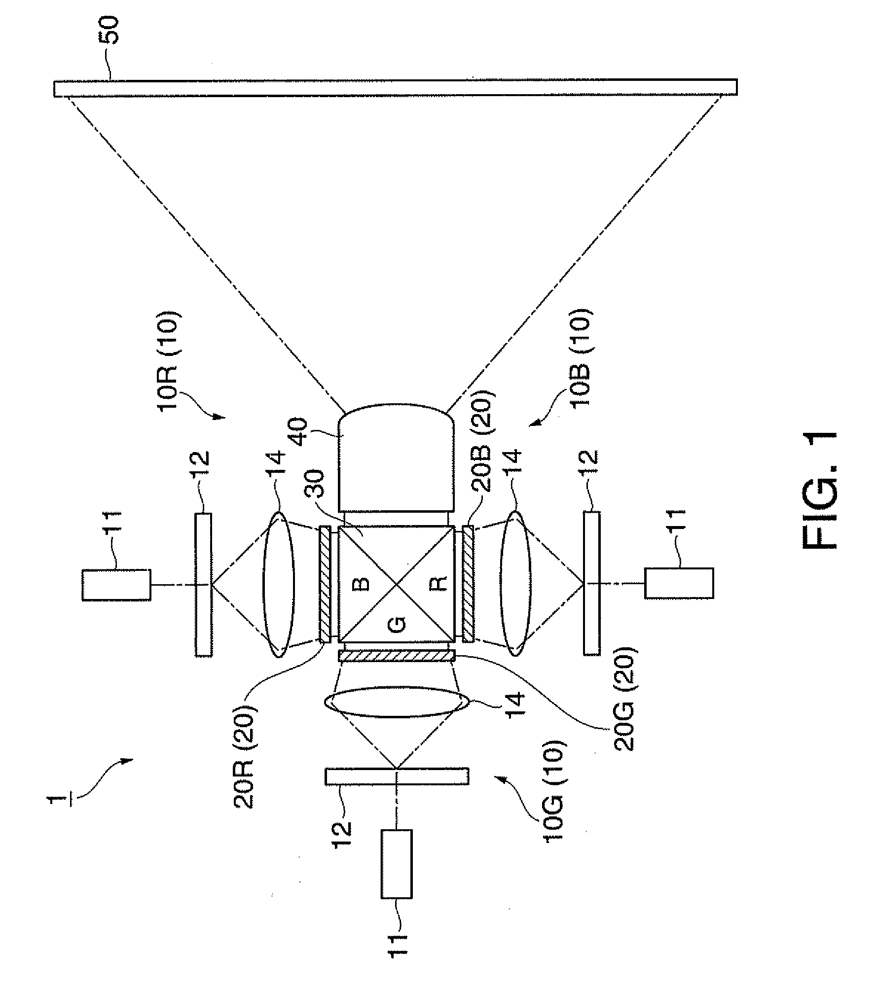
[0080]In a projector (image display apparatus) 1 according to the present embodiment using a reflective screen (surface on which light is projected) 50, light containing image information is projected on the screen 50 from the front side thereof, as shown in FIG. 1.

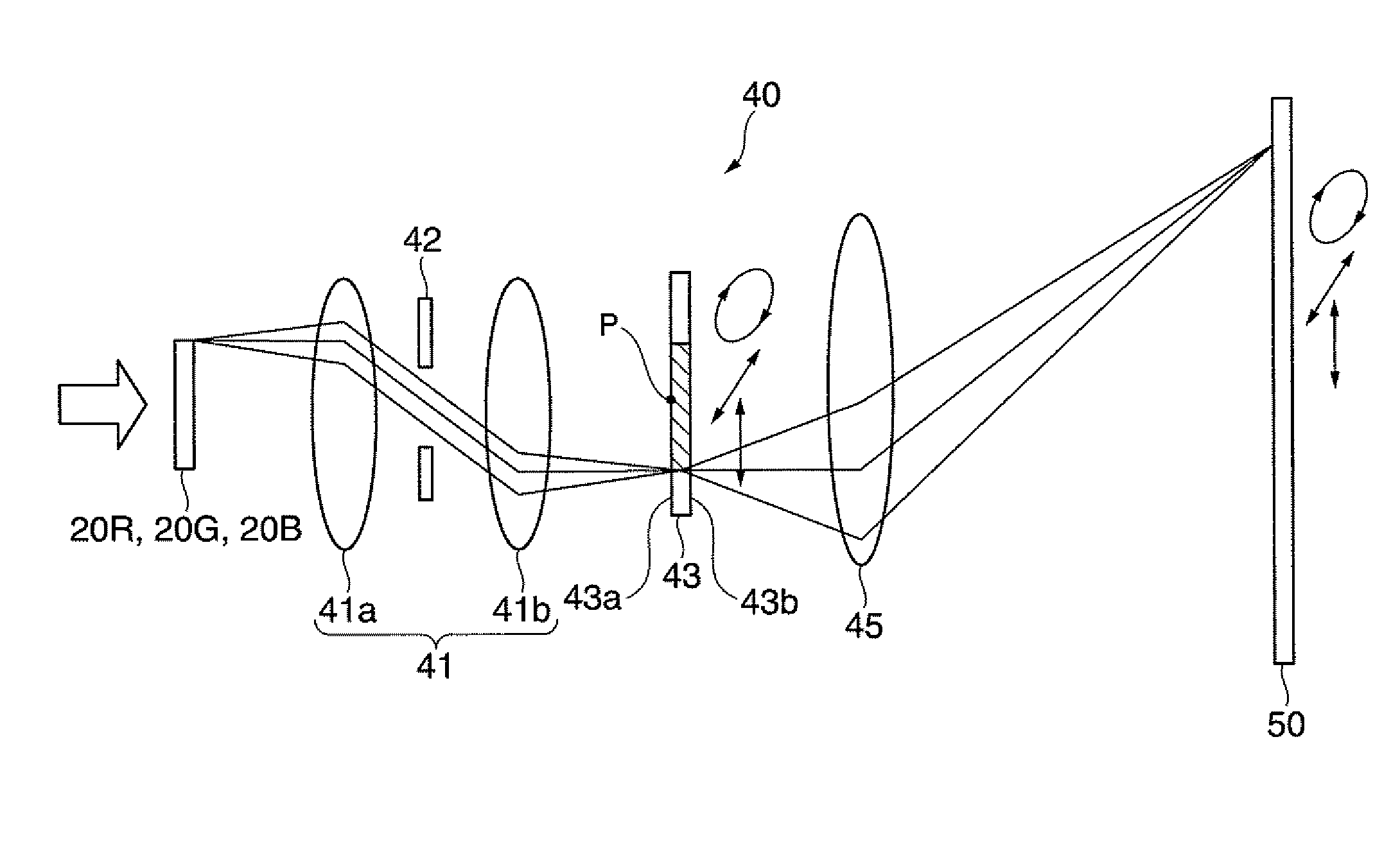
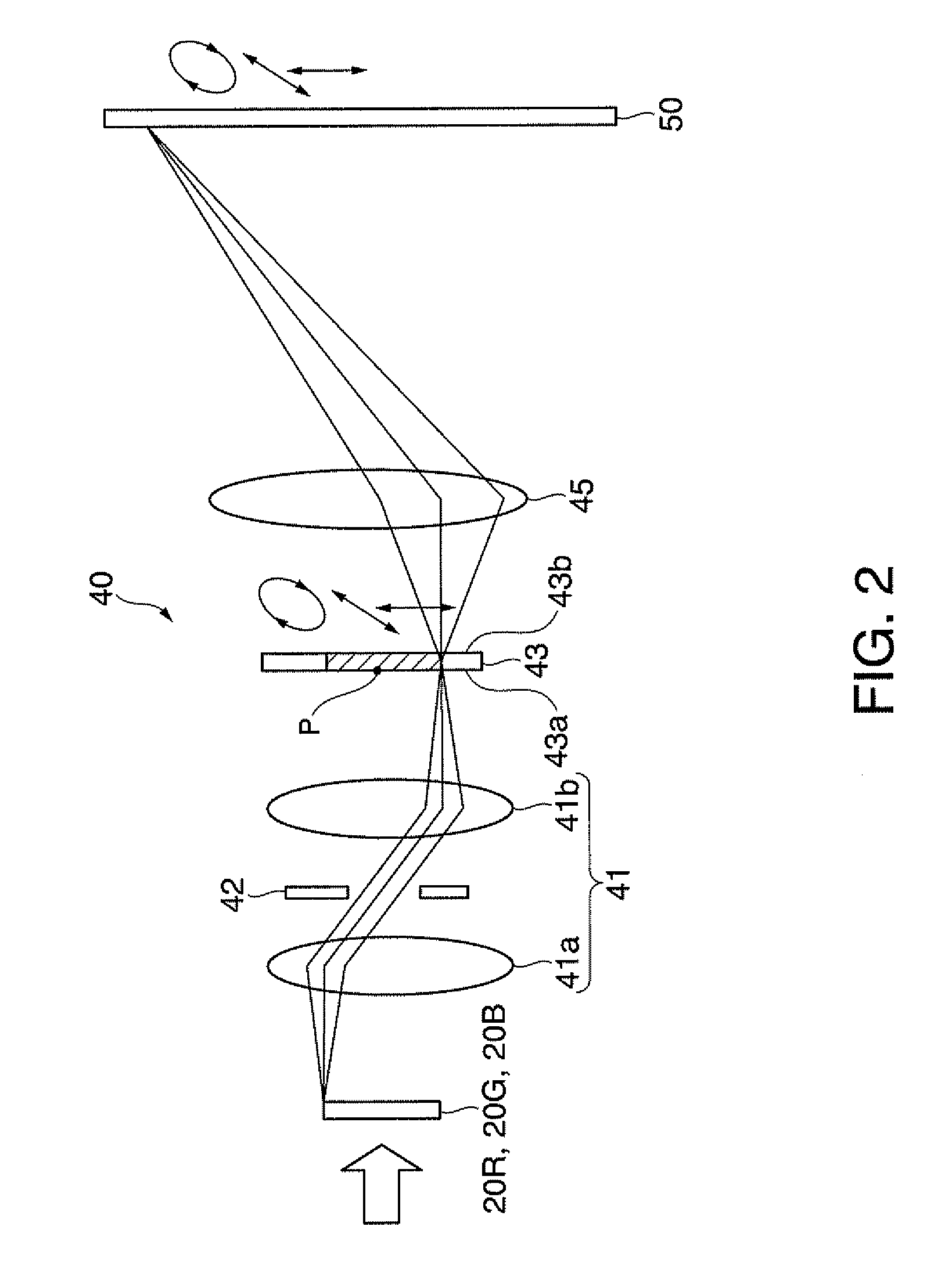
[0081]The projector 1 includes a light source apparatus (laser light source) 10, a light modulator 20, a dichroic prism (color light combiner) 30, and a projection system (projection device) 40. In the following description, the light modulator is referred to as a liquid crystal light valve.

[0082]The light source apparatus 10 includes a red light source apparatus (laser light source) 10...

second embodiment

[0116]A second embodiment according to the invention will be described with reference to FIG. 6. In the drawings of the embodiments described below, the same portions as those in the projector 1 according to the first embodiment described above have the same reference characters, and no description of those portions will be made.

[0117]A projector 60 according to the present embodiment is similar to the first embodiment but differs therefrom in that the same polarization converter plate 43 as that in the first embodiment is disposed on the optical path between a light source (laser light source) 61 and a reflective light valve 64.

[0118]The projector (image display apparatus) 60 includes, as shown in FIG. 6, a light source 61, a hologram element 62, a polarization converter plate (polarization converter) 43, a parallelizing lens 63, a reflective light valve (reflective light modulator) 64, and a projection system (projection device) 65.

[0119]The light source 61 is an LD (Laser Diode) ...

third embodiment

[0130]A third embodiment according to the invention will be described with reference to FIG. 7.

[0131]A projector (image display apparatus) 70 according to the present embodiment differs from the second embodiment in that a polarization converter plate 51 and a light diffuser plate 52 are separately provided.

[0132]The polarization converter plate (polarization converter) 51 is disposed on the optical path between the hologram element 62 and the parallelizing lens 63, as shown in FIG. 7. The polarization converter plate 51 is made of polycarbonate and differentiates the polarization directions of the laser light that has exited from the hologram element 62 and is then incident on areas of the polarization converter plate 51. The polarization converter plate 51 may be disposed anywhere on the optical path between the light source 61 and the reflective light valve 64.

[0133]The light diffuser plate (light diffusion section) 52 is disposed on the optical path between the reflective light ...


PUM


Abstract

An illuminator that illuminates a projected surface includes a laser light source that emits laser light; a polarization converter disposed downstream of the laser light source, the polarization converter having a first area that converts the polarization direction of incident laser light into a first polarization direction and outputs the resultant laser light and a second area that converts the polarization direction of incident laser light into a second polarization direction and outputs the resultant laser light; and a light diffusion section disposed downstream of the laser light source, the light diffusion section diffusing incident laser light.

Description

BACKGROUND[0001]1. Technical Field[0002]The present invention relates to an illuminator, an image display apparatus, and a polarization conversion / diffusion member.[0003]2. Related Art[0004]In recent years, there is widely known a projector in which an illuminator illuminates a light modulator and a projection optical system, such as a projection lens, enlarges and projects image light outputted from the light modulator on a screen.[0005]A metal halide lamp, a halogen lamp, and other lamps have been used as the illuminator in the projector. In recent years, however, it has been proposed to use a semiconductor laser (LD) to reduce the sizes of the illuminator and the projector. Advantages of a laser light source include not only compactness but also excellent color reproducibility, image display with high brightness and contrast, and quick start.[0006]However, since laser light is coherent, enlarged and projected image light produces a speckle pattern having bright and dark dots rand...

Claims


Application Information

Patent Timeline
IPC IPC(8): G02B27/18G03B21/14G02B27/28
CPCG02B27/281G03B33/12G03B21/14G02B27/48G03B21/2073G03B21/208
Inventor YAMAUCHI, TAISUKETAKEDA, TAKASHI
Owner COLUMBIA PEAK VENTURES LLC
Why Eureka
Try Eureka