Solid electrolytic capacitor

a technology of solid electrolytic capacitors and capacitors, which is applied in the manufacture of electrolytic capacitors, liquid electrolytic capacitors, electrolytic capacitors, etc., can solve the problem of limiting the reduction of equivalent series resistance, and achieve the effect of reducing the equivalent series resistance and reducing the effective contact area

Active Publication Date: 2009-06-25
SANYO ELECTRIC CO LTD
View PDF26 Cites 31 Cited by
  • Summary
  • Abstract
  • Description
  • Claims
  • Application Information

AI Technical Summary

Benefits of technology

[0007]The ridges and valleys on the surface of the conductive polymer layer formed by mixing powder, such as graphite powder, increases contact area in the interface between the conductive polymer layer and the conductive carbon layer. However, ridges and valleys reflecting the surface state of the conductive polymer layer are formed in the surface of the conductive carbon layer. The silver particles contained in the silver paste may not enter some of the valleys in the surface of the conductive carbon layer. In such a case, the effective contact area between ...

Problems solved by technology

This limits the reduction in the equivalent series resistance when ...

Method used


Image

  • Solid electrolytic capacitor
  • Solid electrolytic capacitor

Examples


example 1

[0045]In example 1, a solid electrolytic capacitor A1 was fabricated through steps 1A to 9A, which respectively corresponds to the above-described steps 1 to 9.

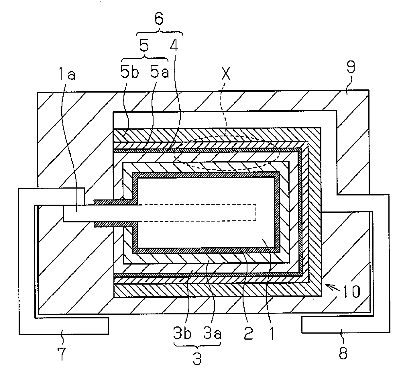
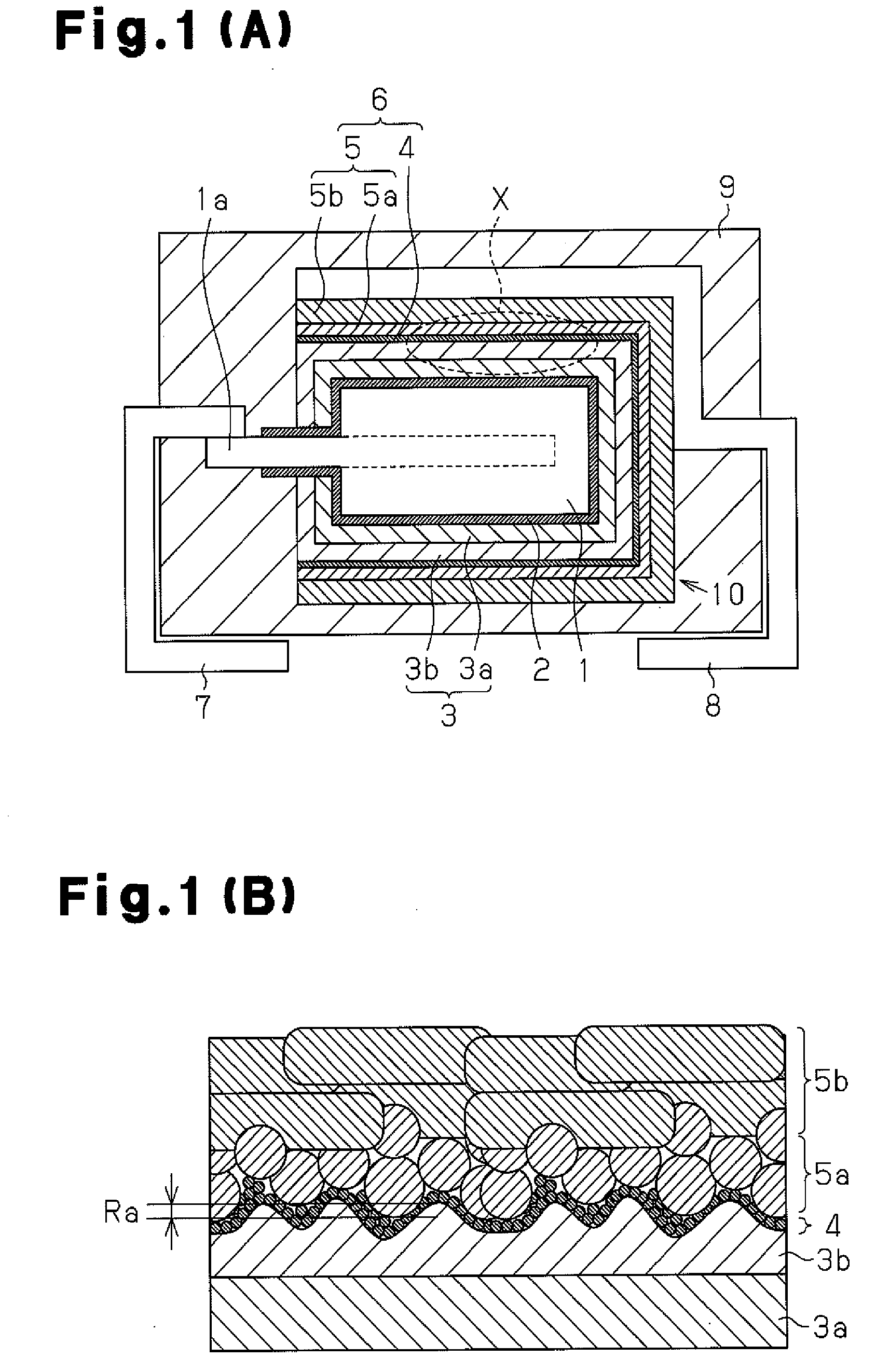
[0046]Step 1A: Niobium metal powder having a CV value of 150,000 μF·V / g was prepared. The CV value is the product of the capacitance of the niobium porous sintered body and the electrolysis voltage after the formation of the electrolytic oxidation coating (dielectric layer). Molding was performed with the niobium metal powder so as to embed part of the anode lead 1a therein and then sintered in a vacuum environment at a temperature of approximately 1,200° C. This formed a niobium porous sintered body functioning as the anode body 1. The distal portion of the anode lead 1a was extended out of the anode body 1. The niobium metal particles were fused together during the sintering. Gaps formed between the niobium particles were reduced in size by the sintering. Unless otherwise mentioned, the CV value of the sintered body in each...

examples 2 to 4

[0074]In examples 2 to 4, solid electrolytic capacitors A2 to A4 were fabricated in the same manner as in example 1 except in that glass abrasive grains having an average grain diameter of 80 μm were blasted under a blasting pressure of 0.3 kg / cm2, 0.6 kg / cm2, and 1.0 kg / cm2 (projection distance 15 cm, processing time three minutes) in step 4A.

examples 5 to 9

[0075]In examples 5 to 9, solid electrolytic capacitors A5 to A9 were fabricated in the same manner as in example 1 except in that glass abrasive grains having an average grain diameter of 100 μm were blasted under a blasting pressure of 0.6 kg / cm2, 1.0 kg / cm2, 1.5 kg / cm2, 2.5 kg / cm2 and 5.0 kg / cm2 (projection distance 15 cm, processing time three minutes) in step 4A.


PUM

PropertyMeasurementUnit
Particle diameteraaaaaaaaaa
Surface roughnessaaaaaaaaaa

Abstract

A solid electrolytic capacitor including an anode body, a dielectric layer arranged on the anode body, a conductive polymer layer arranged on the dielectric layer, and a cathode layer including a carbon layer arranged on the conductive polymer layer and a silver layer arranged on the carbon layer. The conductive polymer layer includes ridges and valleys formed in a surface that faces toward the cathode layer. The silver layer includes a first silver layer, which is arranged on the carbon layer, covers the ridges and valleys, and mainly contains spherical silver particles, and a second silver layer, which is arranged on the first silver layer and mainly contains silver flakes.

Description

CROSS-REFERENCE TO RELATED APPLICATIONS[0001]This application is based upon and claims the benefit of priority from prior Japanese Patent Application No. 2007-329607, filed on Dec. 21, 2007, the entire contents of which are incorporated herein by reference.BACKGROUND OF THE INVENTION[0002]The present invention relates to a solid electrolytic capacitor.[0003]Solid electrolytic capacitors have superior high frequency characteristics and large capacities in addition to being compact. Thus, solid electrolytic capacitors are widely used in high frequency circuits of various types of electronic devices such as personal computers and imaging devices.[0004]A typical method for manufacturing a solid electrolytic capacitor will now be discussed. First, powders of valve metals such as niobium (Nb) and tantalum (Ta) are pressurized and molded to form with an anode lead and then sintered to form a sintered body. The sintered body is then anodized to form a dielectric layer, which mainly includes...

Claims


Application Information

Patent Timeline
IPC IPC(8): H01G9/042H01G9/15H01G9/048H01G13/00H01G9/00H01G9/028H01G9/04
CPCH01G9/0425H01G9/15H01G11/48Y10T29/417H01G2/06Y02E60/13H01G2/065
Inventor NEMOTO, MASAAKIUMEMOTO, TAKASHINONOUE, HIROSHI
Owner SANYO ELECTRIC CO LTD
Why Eureka
Try Eureka