Heat treatment method, heat treatment apparatus and substrate processing apparatus

a heat treatment apparatus and substrate technology, applied in heat treatment apparatus, lighting and heating apparatus, applications, etc., can solve the problems of low-k film degradation (oxidation), difficult to make a complete vacuum or nitrogen gas atmosphere, worrisome possibility, etc., to prevent the degradation of a specific coating film, and reduce the difficulty of oxidation.

Inactive Publication Date: 2009-06-25
TOKYO ELECTRON LTD
View PDF8 Cites 322 Cited by
  • Summary
  • Abstract
  • Description
  • Claims
  • Application Information

AI Technical Summary

Benefits of technology

[0023]In accordance with the first and second aspects of the present invention, after a coating film or low-k film is formed on a substrate, the substrate is heated under an atmosphere of an organic compound having higher reducibility than hydrogen and ammonia. Accordingly, a heat treatment can be performed on the substrate while oxygen in the heating atmosphere is efficiently removed by a reduction reaction of the organic compound. Thus, it is possible to prevent degradation of a specific coating film or low-k film.
[0024]Further, in accordance with the third to seventh aspects of the present invention, after a coating film or low-k film is formed on a substrate, the substrate is loaded into a processing chamber and a gaseous organic compound having higher reducibility than hydrogen and ammonia is supplied into the processing chamber. Then, the substrate is heated in the processing chamber supplied with the organic compound. Accordingly, the organic compound can be efficiently filled in the processing chamber, and a heat treatment can be performed on the substrate while oxygen in the heating atmosphere is efficiently removed by a reduction reaction of the organic compound. Thus, it is possible to prevent degradation of a specific coating film or low-k film.

Problems solved by technology

However, it is very difficult to make a complete vacuum or nitrogen gas atmosphere, and impurities such as oxygen can be easily contained in the atmosphere.
Accordingly, in these methods, there is a worrisome possibility that the low-k film may be degraded (oxidized) due to oxygen contained in the atmosphere.
However, it is difficult to completely prevent degradation of the low-k film with reactivity of a hydrogen gas or ammonia gas.

Method used


Image

  • Heat treatment method, heat treatment apparatus and substrate processing apparatus
  • Heat treatment method, heat treatment apparatus and substrate processing apparatus
  • Heat treatment method, heat treatment apparatus and substrate processing apparatus

Examples


Embodiment Construction

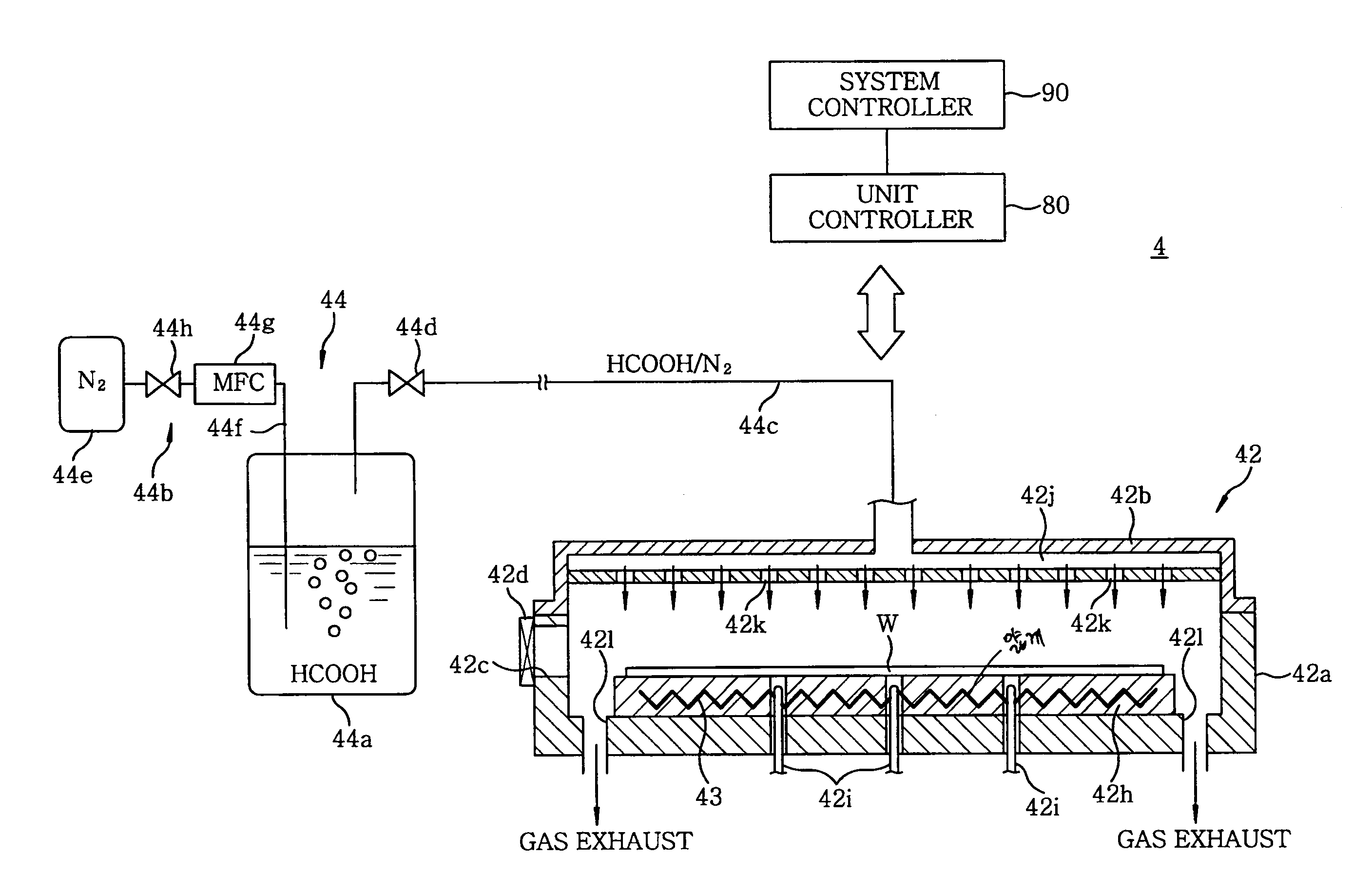
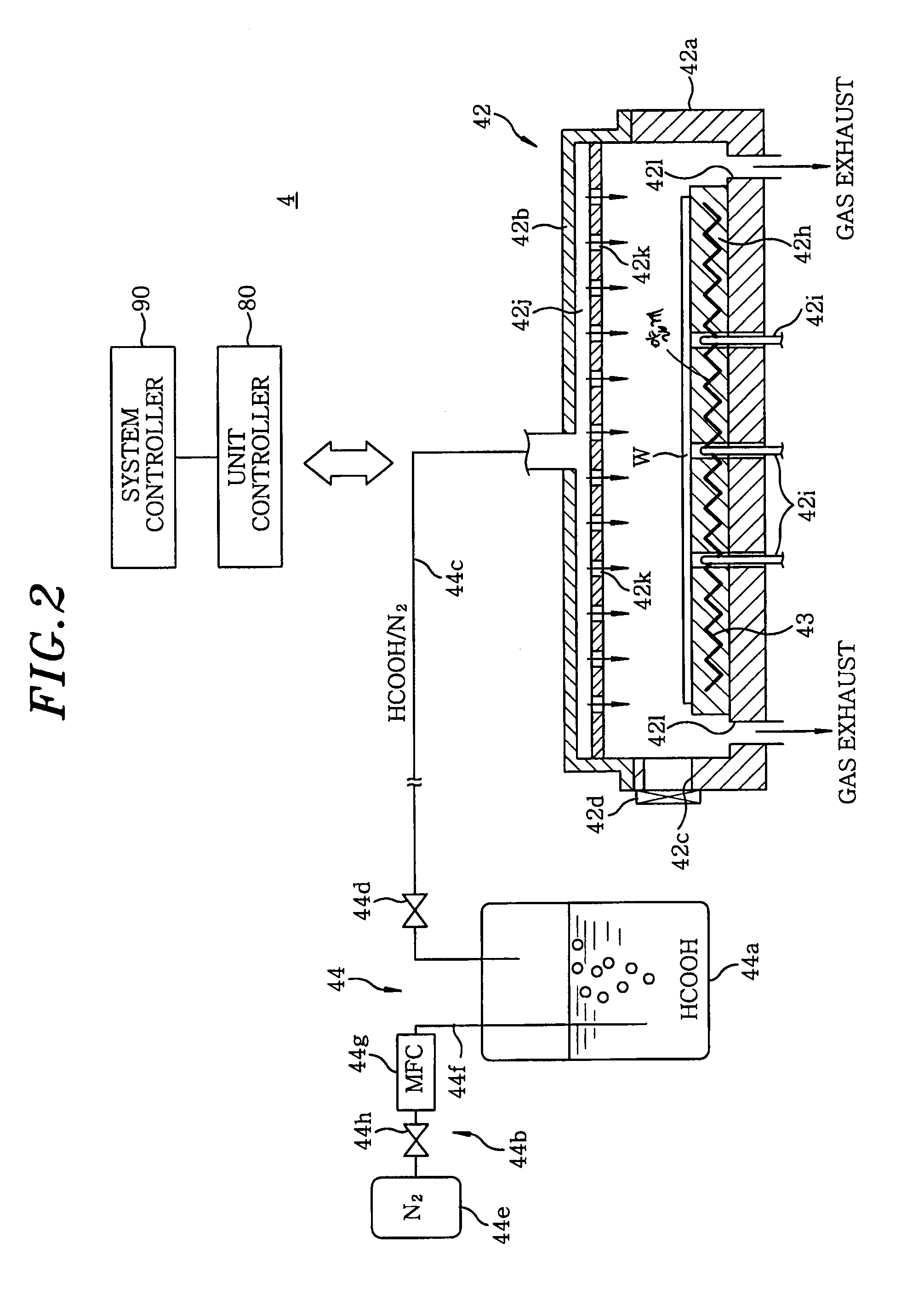
[0030]Hereinafter, embodiments of the present invention will be described in detail with reference to the accompanying drawings which form a part hereof.

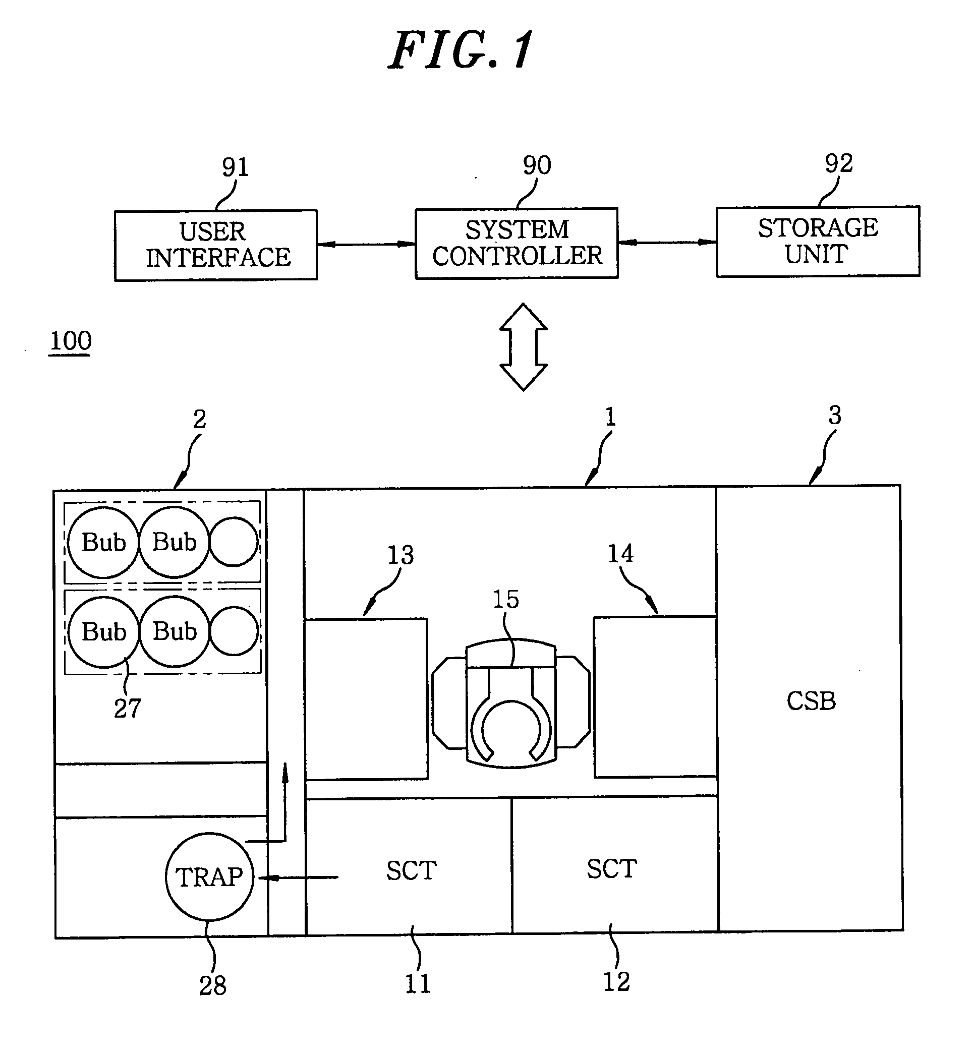
[0031]FIG. 1 schematically shows a plan view of an SOD system including a heat treatment unit capable of performing a heat treatment method in accordance with the present invention.

[0032]The SOD system (substrate processing apparatus) 100 includes a processing section 1, a side cabinet 2 and a carrier station (CSB) 3. The side cabinet 2 and the carrier station (CSB) 3 are disposed at opposite sides of the processing section 1, respectively.

[0033]The processing section 1 includes coating process units (SCT) 11 and 12, processing unit sets 13 and 14 each having a plurality of processing units stacked in multiple levels, and a transfer arm 15 for transferring a semiconductor wafer (substrate) W therebetween. The transfer arm 15 is disposed in a central portion of the processing section 1. The processing unit sets 13 and 14 are disposed...


PUM

PropertyMeasurementUnit
dielectric constantaaaaaaaaaa
pressureaaaaaaaaaa
sizeaaaaaaaaaa

Abstract

Disclosed is a heat treatment unit 4 serving as a heat treatment apparatus, which includes a chamber 42 for containing a wafer W on which a low dielectric constant interlayer insulating film is formed, a formic acid supply device 44 for supplying gaseous formic acid into the chamber 42, and a heater 43 for heating the wafer W in the chamber 42 which is supplied with formic acid by the formic acid supply device 44.

Description

FIELD OF THE INVENTION[0001]The present invention relates to a heat treatment method and a heat treatment apparatus for performing a heat treatment on a substrate having a specific coating film or a substrate having an interlayer insulating film of a low dielectric constant (low-k film) and a substrate processing apparatus including the heat treatment apparatus.BACKGROUND OF THE INVENTION[0002]Recently, a semiconductor device has been designed to have multilayer interconnection for the purpose of improving its operating speed and reducing its size. Further, it is necessary to reduce resistances of lines and electric capacitances between lines in order to increase its operating speed. Accordingly, copper (Cu) having a low resistance is widely used in the lines, and a low dielectric constant material is widely used in an interlayer insulating film provided between the Cu lines to reduce capacitance between the Cu lines.[0003]The interlayer insulating film made of a low dielectric cons...

Claims


Application Information

Patent Timeline
Patent Type & Authority Applications(United States)
IPC IPC(8): H01L21/3105C23C16/54H01L21/26
CPCH01L21/02126H01L21/02337H01L21/3122H01L21/3124H01L21/76828H01L21/31633H01L21/31695H01L21/76814H01L21/76826H01L21/31629H01L21/02216
Inventor MIYOSHI, HIDENORI
Owner TOKYO ELECTRON LTD
Why Eureka
Try Eureka