
Flexible Stent-Graft Device Having Patterned Polymeric Coverings

a flexible, polymer-based technology, applied in the field of implantable prosthesis, can solve the problems of plastic deformation of the stent-graft endoprosthesis, prone to leakage of blood therethrough, physical deformation, etc., to improve flexibility, reduce stiffness and permeability, and increase longitudinal flexibility

Inactive Publication Date: 2009-06-25
LIFESHIELD SCI
View PDF25 Cites 73 Cited by
  • Summary
  • Abstract
  • Description
  • Claims
  • Application Information

AI Technical Summary

Benefits of technology

[0019]One advantage of the present invention is that it provides an endoluminal prosthesis including a stent covered with a graft providing increased longitudinal flexibility, especially within certain defined regions.
[0020]The graft may be made from polymeric graft material, such as a polyester, a polypropylene, a polyethylene, a polyurethane, a polynaphthalene, a polytetrafluoroethylene, an expanded polytetrafluoroethylene, a silicone, and combinations and copolymers thereof.
[0021]Desirably, the graft is made from a laminated expanded polytetrafluoroethylene. During lamination, there are areas created within the lamination wherein the sintering and consolidation of the expanded polytetrafluoroethylene is affected by dimples in the ePTFE layer. The dimples are formed during the lamination process when air is evacuated through small holes in the lamination mandrel. The dimpled regions thus have lower stiffness and permeability. By exploiting the change in stiffness due to the dimples, a graft can be produced having a particular pattern of dimples to produce regions of increased flexibility.
[0022]The prosthesis of this aspect of the present invention may further include a radially distensible, tubular stent. Desirably, the stent comprises a plurality of undulating stent segments, for example an undulating wire helically wound into a plurality of circumferential windings to define a stent wall structure. The ePTFE graft may be securably attached to at least one of the circumferential windings of the undulating wire and having regions of the ePTFE graft is disposed between at least two adjacent windings of the circumferential windings of the undulating wire. Desirably, the substantially smooth tubular wall is free of folds, crimps and pleats.
[0023]In some embodiments, the present invention provides an endoprosthesis comprising a radially distensible, tubular stent comprising opposed open ends and a stent wall structure having opposed exterior and luminal surfaces; and a continuous and seamless ePTFE tubular covering having a node and fibril structure securably disposed to at least one of the stent surfaces, the graft covering comprising at least two laminated layers, wherein the laminated layers include at least one region where the laminated layers are not securely bonded; and the at least one region has a different bending flexibility from the tubular graft covering.
[0024]In another aspect of the present invention, a method of making a stent-graft having increased bending flexibility is provided. In the efficient attainment of these and other objectives, the method of this aspect of the present invention comprises providing a radially distensible, tubular stent comprising opposed open ends and a stent wall structure having opposed exterior and luminal surfaces, providing a continuously uninterrupted ePTFE tubular graft, the graft securably disposed to one of the stent surfaces, the graft comprising a continuously uninterrupted tubular wall comprising at least two laminated layers, providing at least one region where the laminated layers are not securely bonded; and the at least one region has a different bending flexibility from the tubular graft covering.

Problems solved by technology

Expanded polytetrafluoroethylene grafts, however, are subject to plastic deformation, especially:1) when compressing the stent-graft for loading into the delivery system, 2) delivering the stent-graft through a highly tortuous bodily lumen and 3) during placement / deployment at the target implant site.
Such plastic deformation may lead to the tearing of the ePTFE, leaving the stent-graft endoprosthesis prone to leakage of blood therethrough.
Furthermore, plastic deformation of expanded polytetrafluoroethylene grafts may lead to physical deformities in the graft, such as buckling, which is also undesirable because it may lead to poor blood flow patterns.
Such stent-grafts having a unitary tubular ePTFE covering adhesively secured to the stent, however, do not have differential flexibility associated with the graft to augment bending or plastic deformation of the graft when subjected certain stresses, such as bending stresses during delivery through tortuous bodily lumens or loading into a delivery system.
While such a resulting stent-graft may have additional flexibility as compared to the above-described stent-grafts to Myers et al., the graft wall is non-continuous, thereby not providing by it self a fluid tight graft wall.
While such stent-grafts may have additional flexibility as compared to the above-described stent-grafts to Myers et al., the graft walls are not continuous, thereby not providing by itself a fluid tight graft wall.
While these later patents describe surface modification or ePTFE to increase porosity or surface modification to increase tissue in growth characteristics, these patents fail to describe modification of ePTFE to improve bending characteristics or to improve flexibility of the ePTFE material as compared to untreated ePTFE,
Typical grafts or stent / graft combinations may not always be flexible enough in the desired location.

Method used


Image

  • Flexible Stent-Graft Device Having Patterned Polymeric Coverings
  • Flexible Stent-Graft Device Having Patterned Polymeric Coverings
  • Flexible Stent-Graft Device Having Patterned Polymeric Coverings

Examples


Embodiment Construction

[0031]The following is a detailed description of the preferred embodiments of the present invention. The description is meant to describe the preferred embodiments, and is not meant to limit the invention in any way.

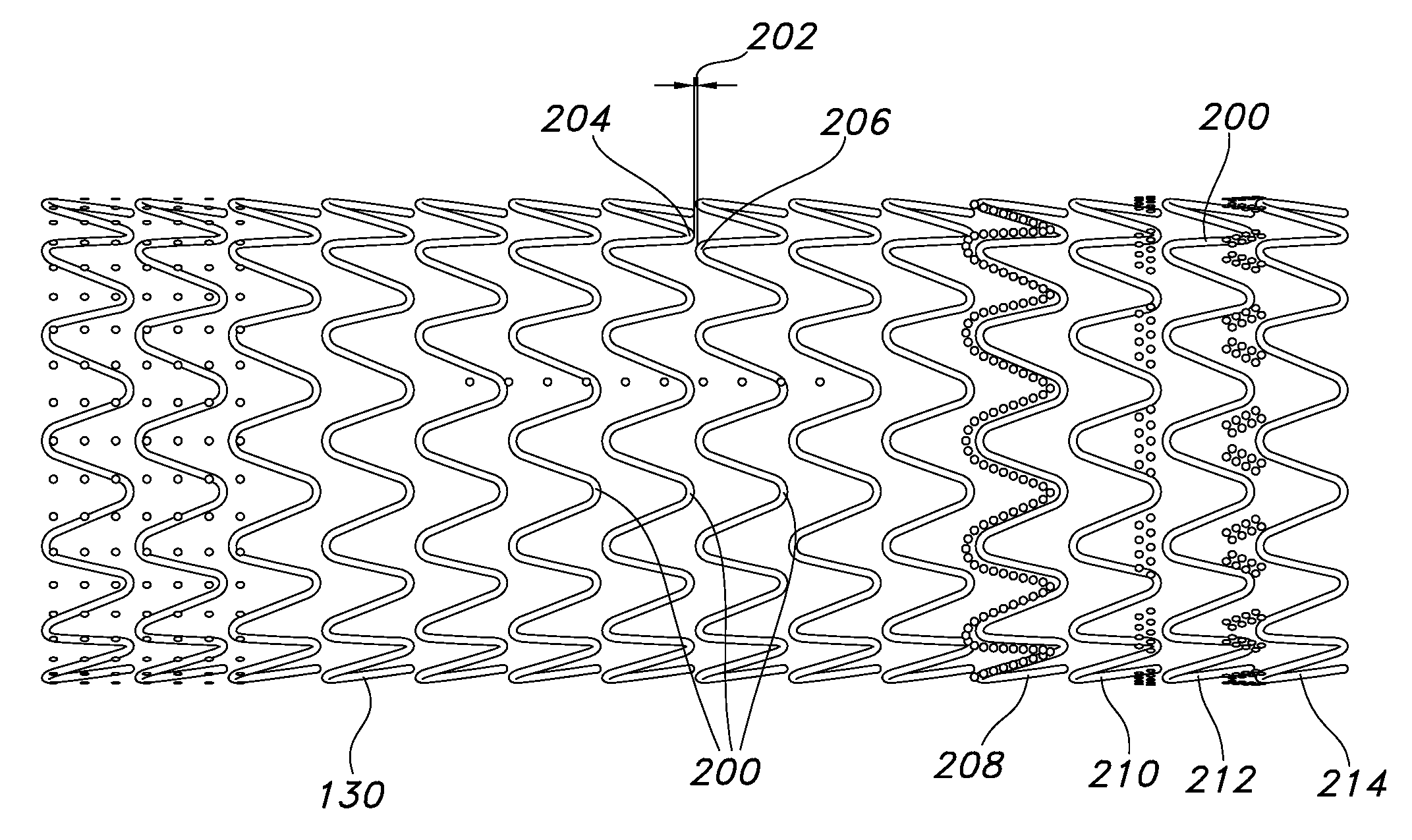
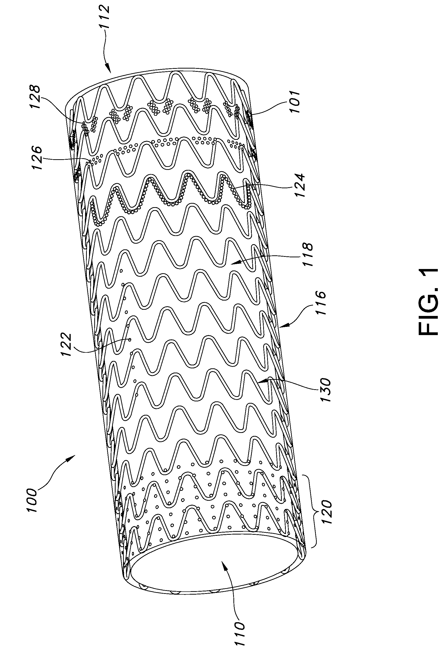
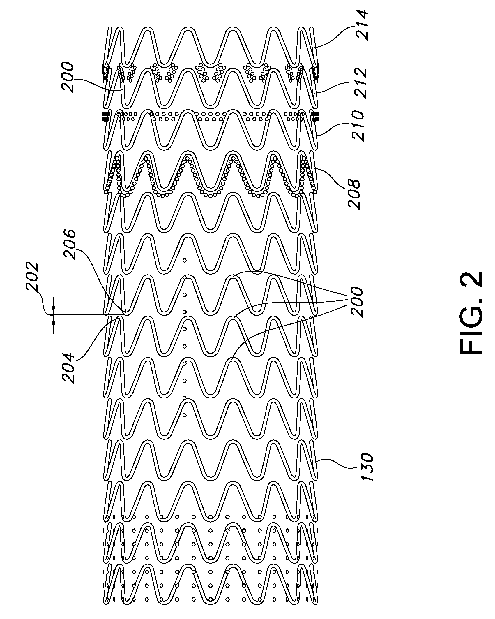
[0032]FIG. 1 is a perspective view of a stent-graft 100 having enhanced flexibility of the present invention. The stent-graft 100 is a hollow, tubular structure or device having opposed open ends 110, 112. The stent-graft 100 includes a tubular wail 116 disposed between the open ends 110, 112. As depicted in FIG. 1, the tubular wall 116 extends along the longitudinal direction. The tubular wall 116 includes a graft 118 having plurality graft portions or regions 120, 122, 124, 126 and 128 that, as described below, have varied or different flexibilities, such as bending flexibilities and will be further described with reference to FIG. 2. The graft wall 116 also extends around the circumference of the stent-graft 100. The tubular wall further includes a stent device 130, w...


PUM


Abstract

The present invention provides an endoprosthesis comprising a radially distensible, tubular stent comprising opposed open ends and a stent wall structure having opposed exterior and luminal surfaces; and a continuous and seamless ePTFE tubular covering having a node and fibril structure securably disposed to at least one of the stent surfaces, the graft covering comprising at least two laminated layers, wherein the laminated layers include at least one region where the laminated layers are not securely bonded; and the at least one region has a different bending flexibility from the tubular graft covering.

Description

CROSS REFERENCE TO RELATED APPLICATION[0001]This patent application claims priority to and the benefit of U.S. Provisional Patent Application No. 61 / 016,160 filed Dec. 21, 2007.FIELD OF THE INVENTION[0002]The present invention relates generally to an implantable prosthesis used to repair or replace a body lumen. More particularly, the present invention relates to an endoluminal prosthesis including a stent and ePTFE graft composite device offering increased compliance and flexibility.BACKGROUND OF THE INVENTION[0003]An endoluminal prosthesis is a medical device commonly known to be used in the treatment of diseased blood vessels. An endoluminal prosthesis is typically used to repair, replace, or otherwise correct a damaged blood vessel. An artery or vein may be diseased in a variety of different ways. The prosthesis may therefore be used to prevent or treat a wide variety of defects such as stenosis of the vessel, thrombosis, occlusion, or an aneurysm.[0004]One type of endoluminal p...

Claims


Application Information

Patent Timeline
IPC IPC(8): A61F2/06
CPCA61F2/07A61F2250/0018A61L31/00A61F2220/0075A61F2002/075A61F2220/0058A61F2/89
Inventor QUIGLEY, FERGUSTHISTLE, ROBERT C.QUINN, WILLIAM
Owner LIFESHIELD SCI
Learn More