Vehicle power controller

a technology for power controllers and vehicles, applied in the direction of motor/generator/converter stoppers, dynamo-electric converter control, capacitor propulsion, etc., can solve the problems of changing braking feeling, and achieve the reduction of regenerative braking force, increasing charging power to secondary batteries, and reducing regenerative braking force

Active Publication Date: 2009-07-02
TOYOTA JIDOSHA KK
View PDF2 Cites 20 Cited by
  • Summary
  • Abstract
  • Description
  • Claims
  • Application Information

AI Technical Summary

Benefits of technology

[0006]The present invention was made to solve the above-described problem, and its object is to provide a power controller for a vehicle including a capacitor charged with regenerative power, which can alleviate change of braking feeling experienced when the regenerative braking force decreases, independent of any power consumption other than power consumption by capacitor charging.
[0007]The present invention provides a power controller that controls a vehicle including a rotating electric machine for running that generates 
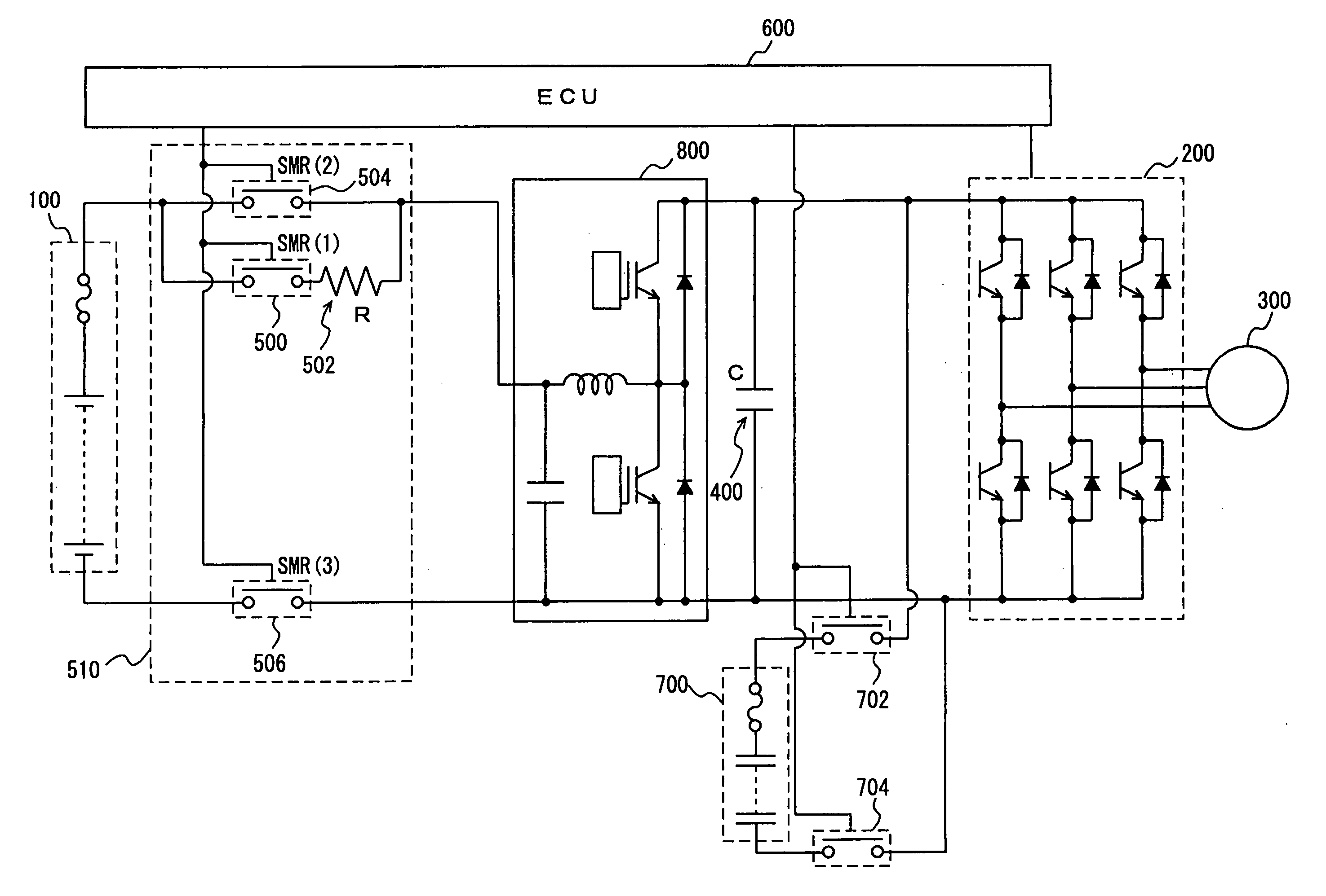
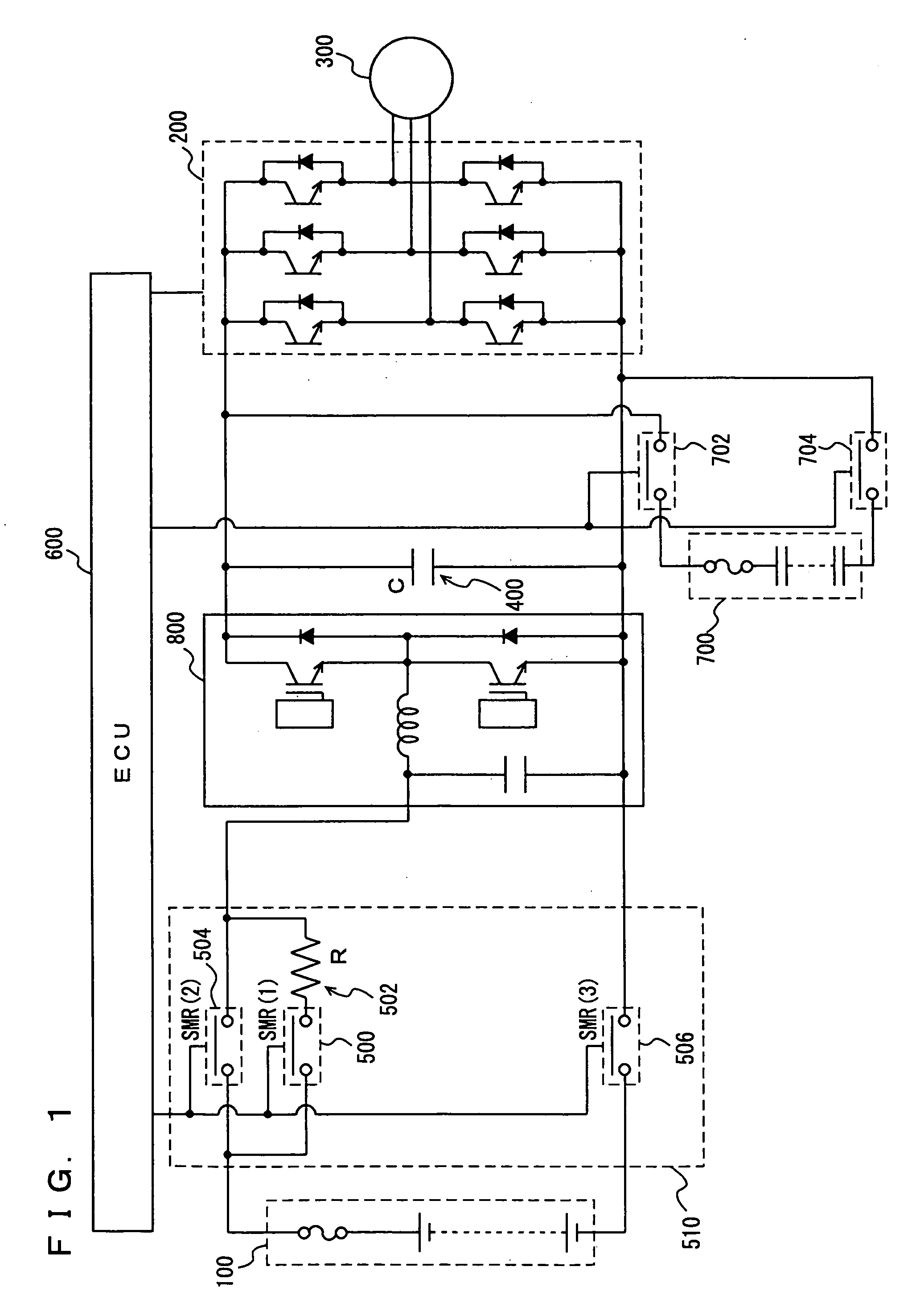
electric power at the time of regenerative braking. The power controller includes a capacitor connected to the rotating electric machine and charged with energy of the generated 
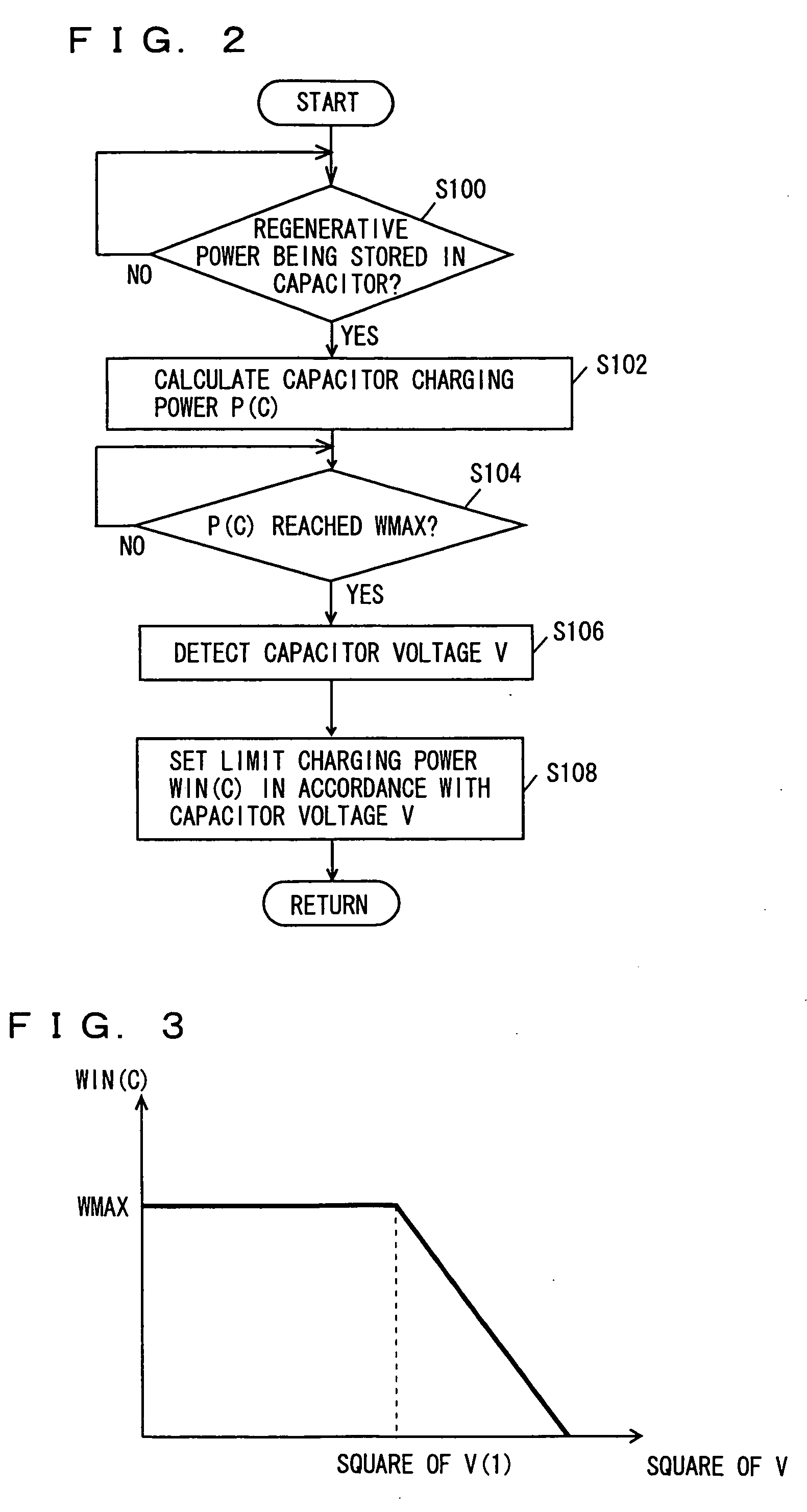
electric power, and an operation unit connected to the capacitor. The operation unit calculates charging power to the capacitor, determines whether the charging power has reached a predetermined upper limit control value or not, and regulates the charging power to be smaller from the time point when the charging power has reached the upper limit control value.
[0008]According to the present invention, the energy generated at the time of regenerative braking (regenerative energy) is stored in the capacitor that has higher charge / discharge efficiency than a battery. Therefore, recovery efficiency of regenerative energy can be improved. In order to prevent instantaneous excessive current and excessive voltage to the capacitor, charging power to the capacitor is limited by a predetermined upper limit value. Further, in order to prevent any damage to the capacitor caused by excessive charging, it is necessary to prevent generation of regenerative energy and to stop charging power to the capacitor, before the capacitor is fully charged. If the charging power is cut from the time point when almost fully charged state has been reached, it would be necessary to abruptly reduce and cut the charging power, because chargeable remaining capacity of the capacitor is small. This might result in reduction of regenerative braking force after cutting the charging power, causing change of braking feeling. Therefore, the charging power to the capacitor is regulated to be smaller from the time point when the upper limit value has been reached. As compared with the cutting of charging power after the time point when almost fully charged state has been reached, chargeable remaining capacity of the capacitor is larger and, therefore, it is possible to moderately reduce and cut the charging power to the capacitor. Therefore, the regenerative braking force reduces moderately. As a result, for a vehicle including a capacitor charged with regenerative power, a power controller that can alleviate change of braking feeling experienced when the regenerative braking force decreases, independent of any power consumption other than that by capacitor charging, can be provided.
[0010]According to the present invention, the amount of charge (amount of electric storage) of the capacitor is generally in proportion to the square of capacitor voltage. It follows that when the capacitor voltage is higher, the capacitor is closer to the fully charged state. Therefore, the charging power to the capacitor is regulated to be smaller in accordance with the capacitor voltage. By way of example, if the capacitor voltage is high, the charging power to the capacitor is made smaller than when the capacitor voltage is lower. Thus, it becomes possible to decrease charging power to the capacitor in accordance with the state of charge of the capacitor. Consequently, it becomes possible to avoid any damage to the capacitor caused by excessive charging.
[0012]According to the present invention, the amount of charge (amount of electric storage) of the capacitor is generally in proportion to the square of capacitor voltage. It follows that when the capacitor voltage is higher, the capacitor is closer to the fully charged state. Therefore, if the capacitor voltage is high, the charging power to the capacitor is regulated to be smaller than when the capacitor voltage is lower. Consequently, it becomes possible to make smaller the charging power to the capacitor as the capacitor comes closer to the fully charged state.
[0018]According to the present invention, by way of example, by controlling the power converted by the converter, the charging power to the secondary battery is increased as the charging power to the capacitor is made smaller. Thus, more moderate reduction of regenerative braking force becomes possible.

Problems solved by technology

This might result in reduction of regenerative braking force after cutting the charging power, causing change of braking feeling.

Method used


Image

  • Vehicle power controller
  • Vehicle power controller
  • Vehicle power controller

Examples


Embodiment Construction

[0023]In the following, an embodiment of the present invention will be described with reference to the figures. In the following description, the same or corresponding portions are denoted by the same reference characters. Their names and functions are also the same. Therefore, detailed description thereof will not be repeated.

[0024]Referring to FIG. 1, the vehicle mounting the power controller in accordance with the embodiment of the present invention will be described. The vehicle includes: a battery 100; an inverter 200; a motor generator 300; a condenser 400; a system main relay 510 (SMR (1) 500, limiting resistor 502, SMR(2) 504, SMR(3) 506); and an ECU (Electronic Control Unit) 600. The power controller in accordance with the present embodiment is controlled by a program executed by ECU 600. In the present embodiment, the vehicle will be described as an electric vehicle that runs only by the driving force from motor generator 300. The vehicle on which power controller of the p...


PUM


Abstract

A power controller alleviating change of braking feeling caused by reduced regenerative braking force is provided. Energy generated by regenerative braking is used for charging a capacitor. The charging power P(C) is calculated and whether P(C) has reached a maximum value WMAX of predetermined limit control value WIN(C) or not is determined. If P(C) is determined to have reached WMAX WIN(C) is regulated to be smaller from that time point.

Description

TECHNICAL FIELD[0001]The present invention relates to power control of a vehicle including a rotating electric machine that generates regenerative power at the time of braking and, more specifically, to power control of a vehicle including a capacitor charged with the regenerative power.BACKGROUND ART[0002]A vehicle mounting a power train referred to as a hybrid system, in which an engine (possibly a known mechanism such as a gasoline engine or a diesel engine) and a motor are combined, has been developed and commercially available. Further, a vehicle (electric vehicle, fuel cell electric vehicle) mounting a power train using only the motor as the running source and not mounting any engine, has also been developed. In such a vehicle, the motor functions as a generator at the time of braking of the vehicle to provide regenerative energy, and the regenerative energy charges an electric storage mechanism (a battery or a capacitor) for motor driving. Consequently, kinetic energy of the ...

Claims


Application Information

Patent Timeline
Patent Type & Authority Applications(United States)
IPC IPC(8): H02P3/14
CPCB60L7/14B60L11/005B60L11/1803B60L11/1861Y02T10/705Y02T10/7005Y02T10/7022Y02T10/7044B60L15/007B60L50/40B60L50/51B60L58/15Y02T10/64Y02T10/70B60W20/00
Inventor SOMA, TAKAYAYOSHIDA, HIROSHIMOGARI, TAKESHI
Owner TOYOTA JIDOSHA KK
Why Eureka
Try Eureka