Ferromagnetic detection enhancer

Active Publication Date: 2009-07-02
KOPP KEITH
View PDF34 Cites 45 Cited by
  • Summary
  • Abstract
  • Description
  • Claims
  • Application Information

AI Technical Summary

Benefits of technology

[0025]In accordance with one feature of the present invention, the sensors are sampled and the data held between magnetization pulses such that the effect of the magnetic field produced by the magnetization pulse will not be represented in the sensor output data. As a result, special sensor or

Problems solved by technology

Although some increased sensitivity is achieved by the use of a primary magnetic field, because of the previously mentioned 5 Gauss safety limit, harder ferromagnetic objects will still not be magnetized and as a result this class of objects will still be hard to detect.
Further, because of the constraints on sensor pair location and orientation and magnetic field uniformity, this apparatus does not lend itself for use in a portal or hand-held wand.
As a result, a significant improvement in detectability of hard ferro

Method used


Image

  • Ferromagnetic detection enhancer
  • Ferromagnetic detection enhancer
  • Ferromagnetic detection enhancer

Examples


Embodiment Construction

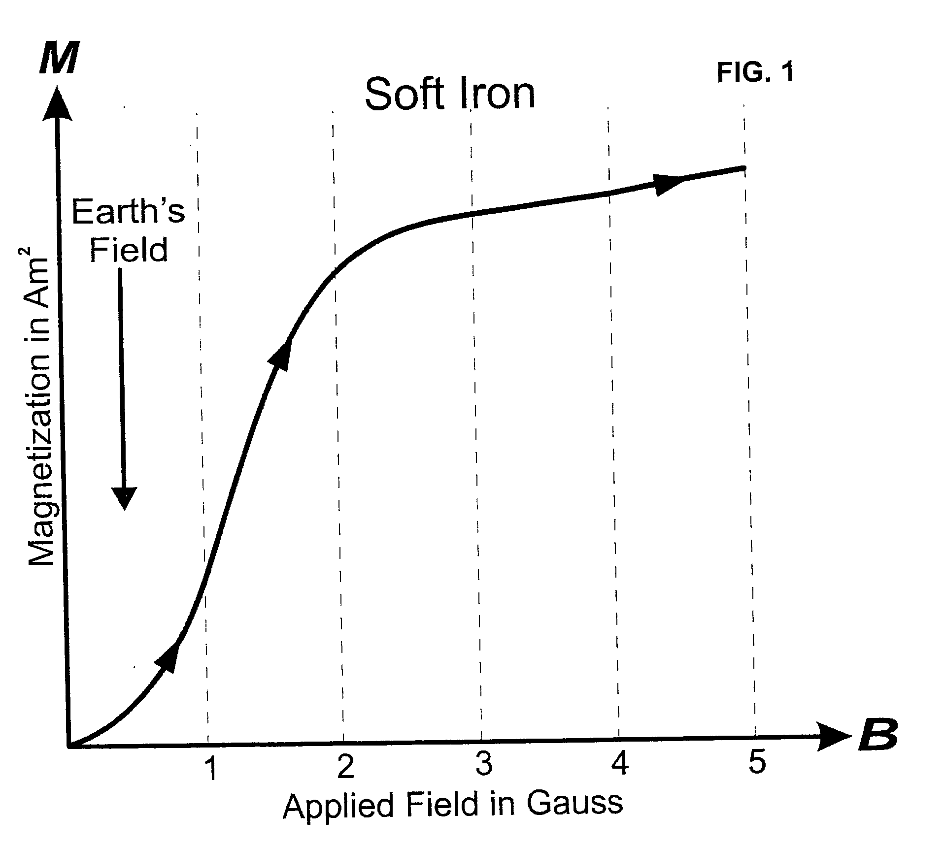
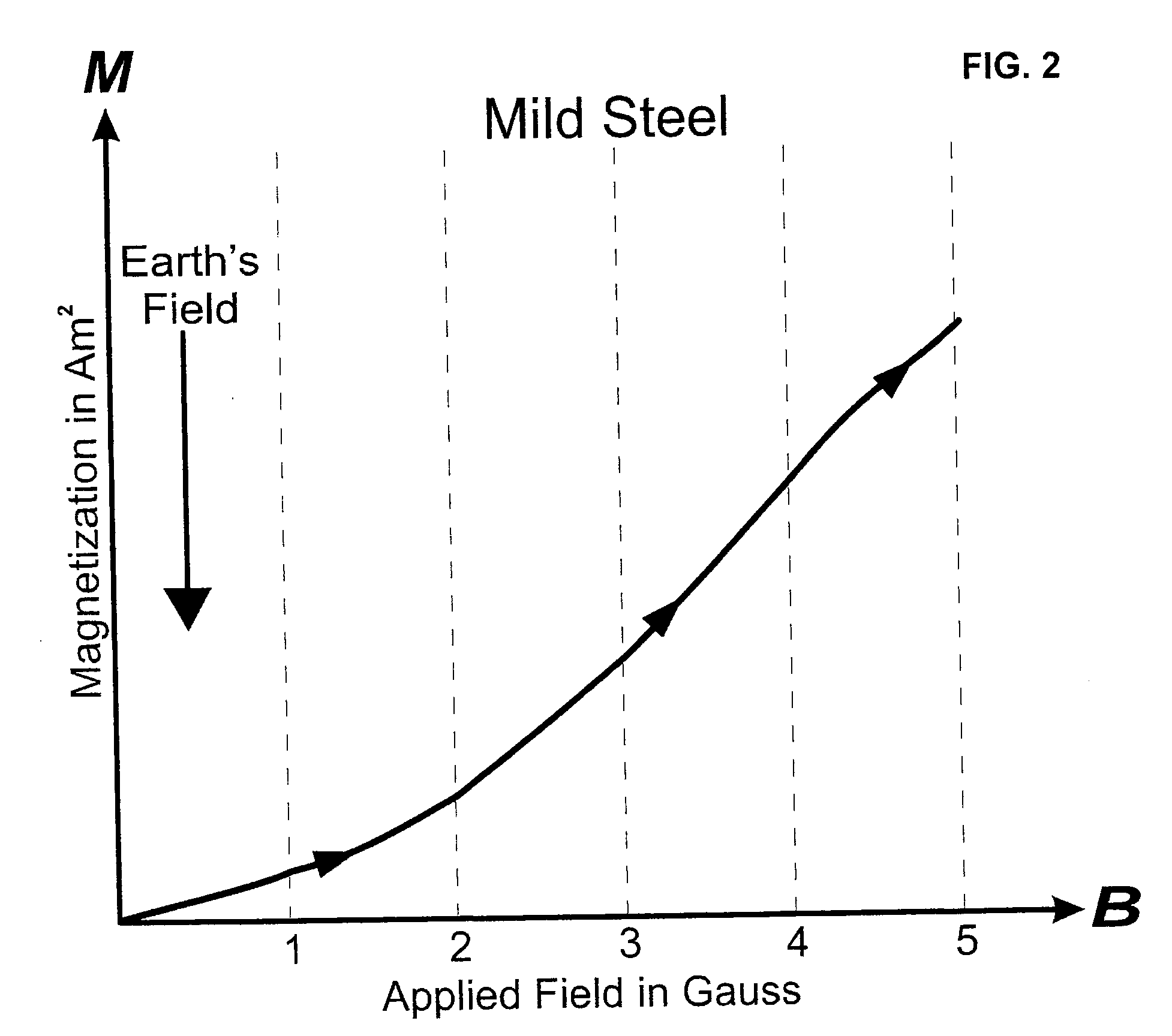
[0040]In accordance with one aspect, the invention can use the fact that ferromagnetic objects that are not appreciably magnetized by the earth's magnetic field will retain a significant level of magnetism for a time after the object is magnetized. This characteristic is called retentivity. For example, a bobby pin retains about one half of its magnetization for a considerable period of time after being exposed to a 100 Gauss magnetic field. As a result, the application of a magnetic field to an object does not have to be coincident in time with the act of screening the ferromagnetic object.

[0041]FIG. 11 is a block diagram of the electronic logic of the present invention. The sequence of events in the invention is controlled by the microprocessor U4. Upon application of power to the device, the microprocessors U4 performs a system check of the sensors S1 through Sn, as well as verifying the operation of the sample and hold circuit U1, the analog to digital converter U2, the pulse ge...


PUM


Abstract

An apparatus for increasing the ability to detect ferromagnetic objects by increasing the magnetization of the objects. The apparatus includes at least one coil to generate a magnetic field positioned in the area of the object to be detected. The apparatus includes an electrical energy storage capacitor bank capable of quickly releasing stored energy. The apparatus includes a high speed, high current electronic switch capable of quickly transferring the stored energy from the capacitor bank to the coil thereby producing in the coil a short duration, single polarity magnetic field pulse. The apparatus includes a sample and hold circuit capable of acquiring magnetic field sensor data during periods when the pulsed magnetic field is not present. The apparatus includes a microprocessor controller to control timing and sequence of the magnetic pulse generation and the sensor data sample and hold process. The apparatus may be for portal handheld or head mounted applications.

Description

CROSS-REFERENCE TO RELATED APPLICATION[0001]This application is a Continuation-In-Part of U.S. utility patent application Ser. No. 10 / 095,543 filed Mar. 11, 2002, from which benefit of priority is hereby claimed.BACKGROUND OF THE INVENTION[0002]1. Field of the Invention[0003]The present invention is in the field of devices or apparatus for detecting ferromagnetic objects in or on personnel in the vicinity of an operating magnetic resonance imaging (MRI) device.[0004]2. Background Art[0005]The MRI has become an invaluable tool for imaging and exploring the internal anatomy without surgery. MRI has the ability to distinguish healthy from diseased tissue, fat and muscle and adjacent structures within the body which other modalities cannot differentiate. MRI uses safe radio waves and a strong magnetic field to generate the information, which is processed by a computer, to create an image. There are now about 10,000 MRI machines currently in use in the United States.[0006]Because of the ...

Claims


Application Information

Patent Timeline
IPC IPC(8): G01R33/28
CPCG01V3/08
Inventor KOPP, KEITH
Owner KOPP KEITH
Why Eureka
Try Eureka