
Detecting pressure pulses in a blood processing apparatus

a technology of pressure pulses and processing equipment, which is applied in the field of detecting pressure pulses in blood processing equipment, can solve problems such as difficult to set appropriate threshold values, subject to blood draining, and potentially life-threatening conditions

Active Publication Date: 2015-10-29
GAMBRO LUNDIA AB
View PDF16 Cites 8 Cited by
  • Summary
  • Abstract
  • Description
  • Claims
  • Application Information

AI Technical Summary

Benefits of technology

The patent text describes a technique for improving the detection of pulsates in a pressure signal obtained from an extracorporeal blood circuit. The technique involves suppressing disturbances that arise from the treatment fluid supply system and other sources to improve the detection of the pulses from the patient. This is done by emulating the signal response of the first pressure sensor using the second pressure sensor and filtering the resulting signal to remove the disturbances. The technique can be used in monitoring patients during surgery or other medical procedures.

Problems solved by technology

In extracorporeal blood processing, it is vital to minimize the risk for malfunctions in the EC circuit, since these may lead to a potentially life-threatening condition of the subject.
Such a disruption may cause the subject to be drained of blood within minutes.
However, it may be difficult to set appropriate threshold values, since the static pressure in the EC blood circuit may vary between treatments, and also during a treatment, e.g. as a result of the subject moving.
Further, if the venous needle comes loose and gets stuck in bed sheets or the subject's clothes, the measured static pressure level might not change enough to indicate the potentially dangerous situation.
Experiments indicate that the pressure variations from the supply system may seriously interfere with the detection of physiological pulses in the pressure signal from the venous pressure sensor.
The Applicant has found it difficult to apply the teachings of aforesaid WO2009 / 156175 to eliminate or suppress the pressure variations that originate from the supply system.
For example, it is non-trivial to utilize a library of predicted signal profiles if the supply system is operated independently of the EC blood circuit and information about the operational state of the supply system is unavailable or incomplete.
Furthermore, the use of predicted signal profiles is likely to result in insufficient removal of pressure variations that are non-repetitive or random, no matter if the predicted signal profiles are generated by reference measurements before the treatment, by reference measurements using a system pressure sensor in the EC blood circuit during the treatment, or by simulations.

Method used


Image

  • Detecting pressure pulses in a blood processing apparatus
  • Detecting pressure pulses in a blood processing apparatus
  • Detecting pressure pulses in a blood processing apparatus

Examples


embodiments

[0063]Throughout the description, the same reference numerals are used to identify corresponding elements.

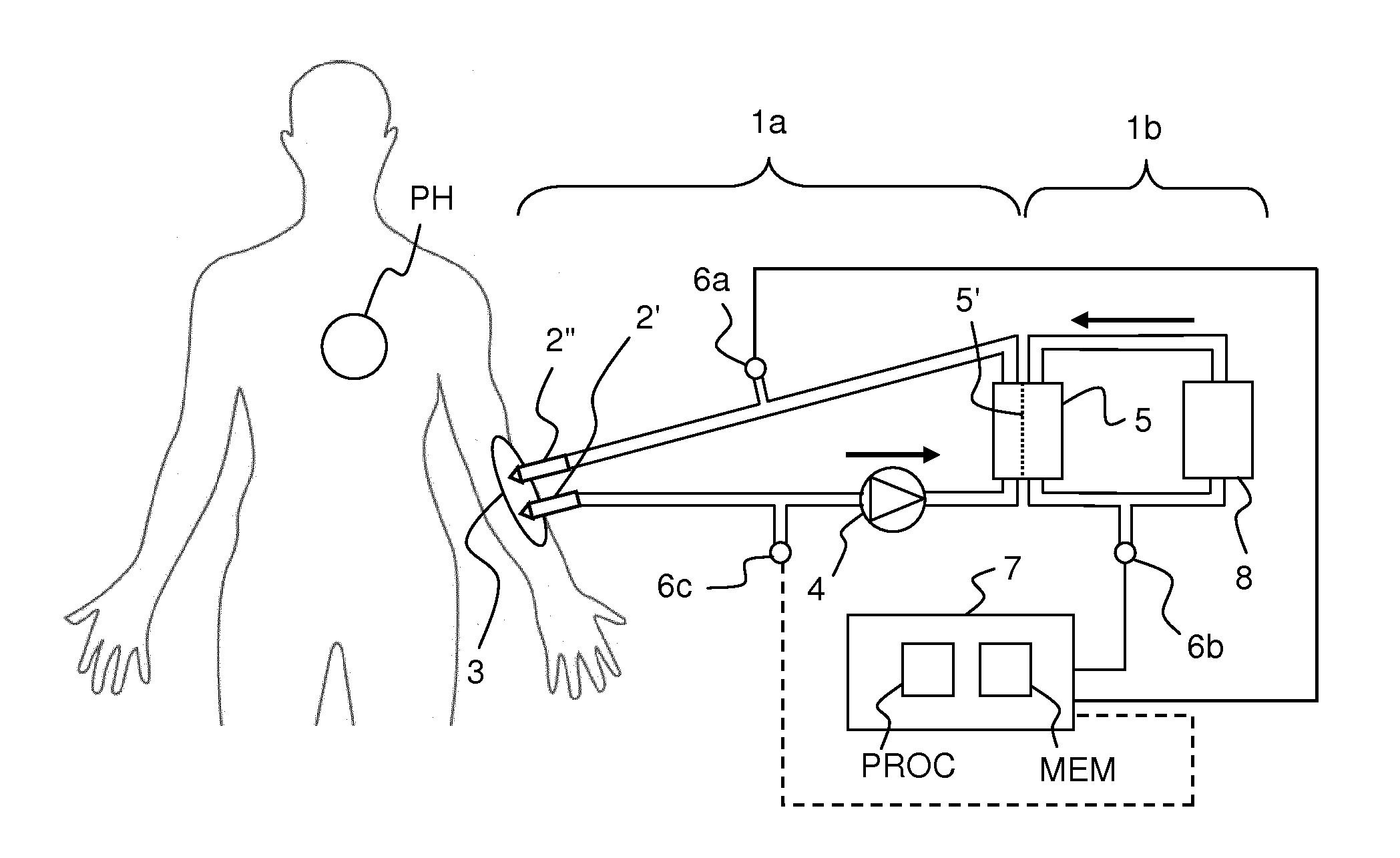
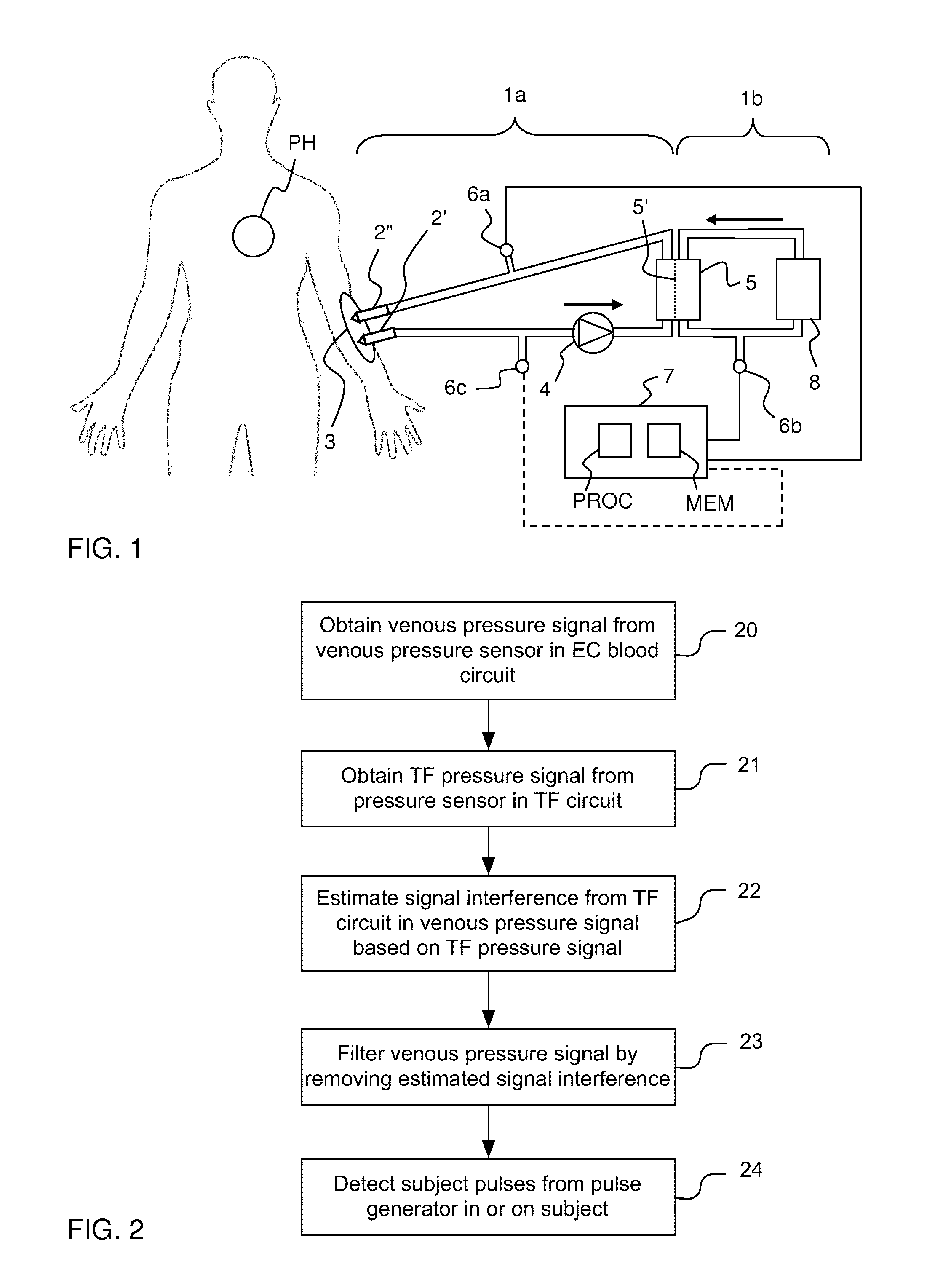
[0064]FIG. 1 illustrates a human subject which is connected to an extracorporeal blood flow circuit 1a by way of access devices 2′, 2″ inserted into a dedicated vascular access 3 (also known as “blood vessel access”) on the subject. The extracorporeal blood flow circuit 1a (denoted “EC circuit” in the following) is configured to communicate blood to and from the cardiovascular system of the subject. In one example, the EC circuit 1a is part of an apparatus for blood processing, such as a dialysis machine (cf. 1 in FIG. 10). In the illustrated example, a blood pump 4 draws blood from the vascular access 3 via access device 2′ and pumps the blood through a blood processing unit 5 and back to the vascular access 3 via access device 2″. Thus, when both access devices 2′, 2″ are connected to the vascular access 3, the EC circuit 1a defines a blood path that starts and ends at the vas...


PUM


Abstract

A monitoring device (7) operates on a pressure signal from a blood processing apparatus, e.g. a dialysis machine, which has an extracorporeal blood circuit connected to a vascular system of a subject for pumping blood through a dialyzer, and a treatment fluid supply system for pumping a treatment fluid through the dialyzer. The monitoring device (7) has a first input block (50) for obtaining a first pressure signal (y) from a first pressure sensor (6a) in the extracorporeal blood circuit, and a second input block (51) for obtaining a second pressure signal (w) from a second pressure sensor (6b) in the treatment fluid supply system. An emulation block (56) generates, as a function of the second pressure signal (w), an emulated first pressure signal (y) which emulates a concurrent signal response of the first pressure sensor (6a), and a filtering block (53) generates a filtered signal (y) as a function of the first pressure signal (y) and the emulated first pressure signal (y), so as to suppress, in the filtered signal (}y) compared to the first pressure signal (y), signal interferences originating from the treatment fluid supply system (1b). A pulse detection block (54) processes the filtered signal (yf) for detection of subject pulses originating from the subject.

Description

TECHNICAL FIELD[0001]The present invention relates to a technique for enabling detection of pulses in a pressure signal from a blood processing apparatus, e.g. a dialysis machine, in particular pulses that originate from a patient which is connected to the blood processing apparatus.BACKGROUND ART[0002]In extracorporeal blood processing, blood is taken out of a human or animal subject, processed (e.g. treated) and then reintroduced into the subject by means of an extracorporeal blood flow circuit (“EC blood circuit”) which is part of a blood processing apparatus. Generally, the blood is circulated through the EC blood circuit by a blood pump. In certain types of extracorporeal blood processing, the EC blood circuit includes an access device for blood withdrawal (e.g. a so-called arterial needle) and an access device for blood reintroduction (e.g. a so-called venous needle), which are inserted into a dedicated blood vessel access (e.g. fistula or graft) on the subject. Such extracorp...

Claims


Application Information

Patent Timeline
IPC IPC(8): A61M1/14
CPCA61M1/14A61M2205/15A61M2230/04A61M2205/3344A61M2205/50A61M2205/3303A61M1/3656A61M1/3653A61M1/3639A61M2205/3331A61M2205/13A61B5/7217A61M1/1605A61M1/1613A61M1/3659A61M1/3661B01D61/32B01D61/30
Inventor STERNBY, JANHOLMER, MATTIASOLDE, BOSOLEM, KRISTIANWALLENBORG, ANDERSHANSSON, PER
Owner GAMBRO LUNDIA AB
Learn More