Energy saving system and method for cooling computer data center and telecom equipment

a technology for telecom equipment and computer data centers, applied in the field of energy saving systems and methods for cooling computer data centers and telecom equipment, can solve the problems of poor turnover of large air mass, insufficient guarantee, and considerable difference between discharging cold air near heat sources, so as to prevent thermal failure of electronic equipment and effectively cool the heat sour

Active Publication Date: 2009-07-02
MARTINI VALAN R
View PDF17 Cites 246 Cited by
  • Summary
  • Abstract
  • Description
  • Claims
  • Application Information

AI Technical Summary

Benefits of technology

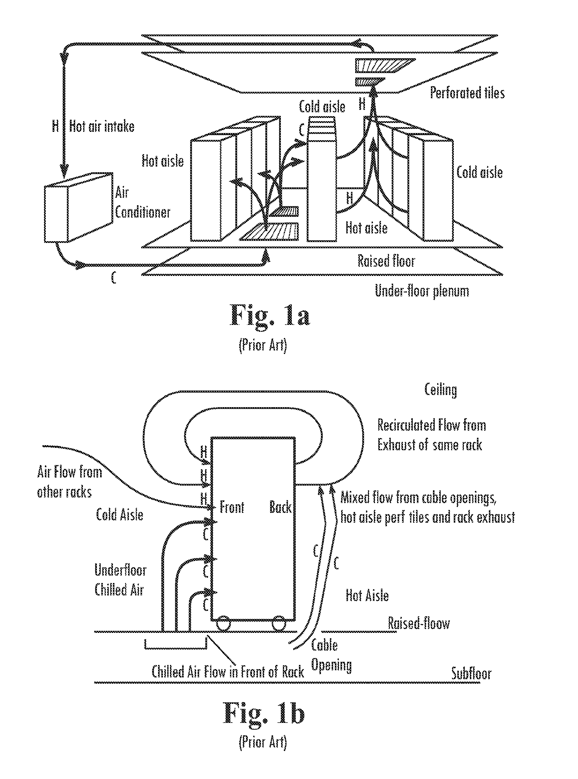
[0012]It is now known that merely locating discharge of cooling air from an air handler near heat producing electronic equipment does not necessarily ensure that the cooling air output is actually providing the desired cooling effect toward preventing thermal failure of the electronic equipment. Indeed, there is a considerable difference between discharging cold air near a heat source, and effectively cooling that heat source in the desired manner. For example, FIG. 1a shows the theoretical delivery of cooling air to computer equipment in a typical “hot aisle-cold aisle” arrangement; whereas FIG. 1b shows the mixing of cooling air with hot air prior to delivery, recirculation of hot air, and insufficient cooling especially at upper rack positions, which commonly occurs in actual practice using known systems and methods for cooling electronic equipment. The chilled air from the air handlers is often blown under an elevated floor with removable tiles. Access flooring tiles can be perforated (having holes drilled through them or other vent configuration) so that the cold air can escape to provide cooling to computers. Col

Problems solved by technology

It is now known that merely locating discharge of cooling air from an air handler near heat producing electronic equipment does not necessarily ensure that the cooling air output is actually providing the desired cooling effect toward preventing thermal failure of the electronic equipment.
Indeed, there is a considerable difference between discharging cold air near a heat source, and effectively cooling that heat source in the desired manner.
Most controlled environment rooms soon become stratified, with a layer of excessively damp, much cooler air flowing along the lowest portion of the environment.
Contrary to common thinking, the reality is that a larger controlled environment with relatively low population of electronic equipment require substantially more cooling due to the high volume of the environment causing poor turnover of the large air mass.
Thus, locating high velocity air handlers too close to equipment can have a very negative effect on the cooling efficiency and cooling performance of the entire above floor environment.
In general, perforated floor tiles have poor output.
As a result

Method used


Image

  • Energy saving system and method for cooling computer data center and telecom equipment
  • Energy saving system and method for cooling computer data center and telecom equipment
  • Energy saving system and method for cooling computer data center and telecom equipment

Examples


Embodiment Construction

[0067]The present invention may be understood more readily by reference to the following detailed description of the invention taken in connection with the accompanying drawing figures, which form a part of this disclosure. It is to be understood that this invention is not limited to the specific devices, methods, conditions or parameters described and / or shown herein, and that the terminology used herein is for the purpose of describing particular embodiments by way of example only and is not intended to be limiting of the claimed invention. Also, as used in the specification including the appended claims, the singular forms “a,”“an,” and “the” include the plural, and reference to a particular numerical value includes at least that particular value, unless the context clearly dictates otherwise. Ranges may be expressed herein as from “about” or “approximately” one particular value and / or to “about” or “approximately” another particular value. When such a range is expressed, another...


PUM


Abstract

A system and method of reducing consumption of electricity used to cool electronic computer data center, networking, and telecommunications equipment, and to reduce the incidence of thermal failure of electronic components, includes provision of one or more partitions to reduce the volume of the cooled environment supplying coldest possible cooled air from air conditioning systems to a chamber adjacent to racks containing the electronic components, preventing dilution of the supplied cooling airflow by warmer air from outside of the reduced volume environment, and controlling the delivery of cooling air flow through the reduced volume of the cooled environment.

Description

CROSS-REFERENCE TO RELATED APPLICATION[0001]This application claims priority benefit to U.S. Provisional Patent Application Ser. No. 60 / 804,908, filed Jun. 15, 2006, which application is hereby incorporated herein by reference in its entirety.TECHNICAL FIELD[0002]The present invention relates generally to an energy saving system and method for reducing electricity used to cool computer data center and telecom equipment by reducing the volume of the cooled environment, controlling airflow, and preventing dilution of the cooling air by warmer air from outside of the cooled environment, and thus increasing cooling airflow, to prevent thermal failure of electronic components.BACKGROUND OF THE INVENTION[0003]Effective cooling of data centers and other facilities operating telecommunications or computer equipment is a growing field of endeavor. Electronic components that operate on the flow of electricity create heat in the process of utilizing electrical flow. Modern electronic equipment...

Claims


Application Information

Patent Timeline
IPC IPC(8): H05K7/20
CPCF24F11/0001F24F2011/0075Y02B30/767H05K7/20745F24F2221/40F24F11/46
Inventor MARTINI, VALAN R.
Owner MARTINI VALAN R
Why Eureka
Try Eureka