Check patentability & draft patents in minutes with Patsnap Eureka AI!

Synchronous rectifier control device and a forward synchronous rectifier circuit

a synchronous rectifier and control device technology, applied in the direction of electric variable regulation, process and machine control, instruments, etc., can solve the problems of power loss, restricted application range of the above-mentioned synchronous rectifier controller,

Inactive Publication Date: 2009-07-02
NIKO SEMICON
View PDF2 Cites 26 Cited by
  • Summary
  • Abstract
  • Description
  • Claims
  • Application Information

AI Technical Summary

Benefits of technology

[0011]In view of the disadvantage that the deadtime period setting of the forward synchronous rectifier circuit is unable to be appropriately adjusted in accordance with application environment, the synchronous rectifier control device of the present invention can adjust the length of the deadtime times based on specified conditions, thus it is possible to satisfy various needs and provides a wider range of applications.

Problems solved by technology

However, since there are forward voltage drop on rectifier diodes D2, D3 when current flows through, power loss thus appears.
Therefore, the application range of the above-mentioned synchronous rectifier controller is restricted.

Method used


Image

  • Synchronous rectifier control device and a forward synchronous rectifier circuit
  • Synchronous rectifier control device and a forward synchronous rectifier circuit
  • Synchronous rectifier control device and a forward synchronous rectifier circuit

Examples


Embodiment Construction

[0021]The present invention employs a simple analog to set a delay time, such that there exists a deadtime period between conducting periods of the rectifier transistor switches on the secondary side of a forward synchronous rectifier device. The above-mentioned analog circuit can adjust the length of the delay time by using the adjustment of capacitance value or resistance value, so as to fulfill different needs found in various application environment, and provide wider range of application flexibility.

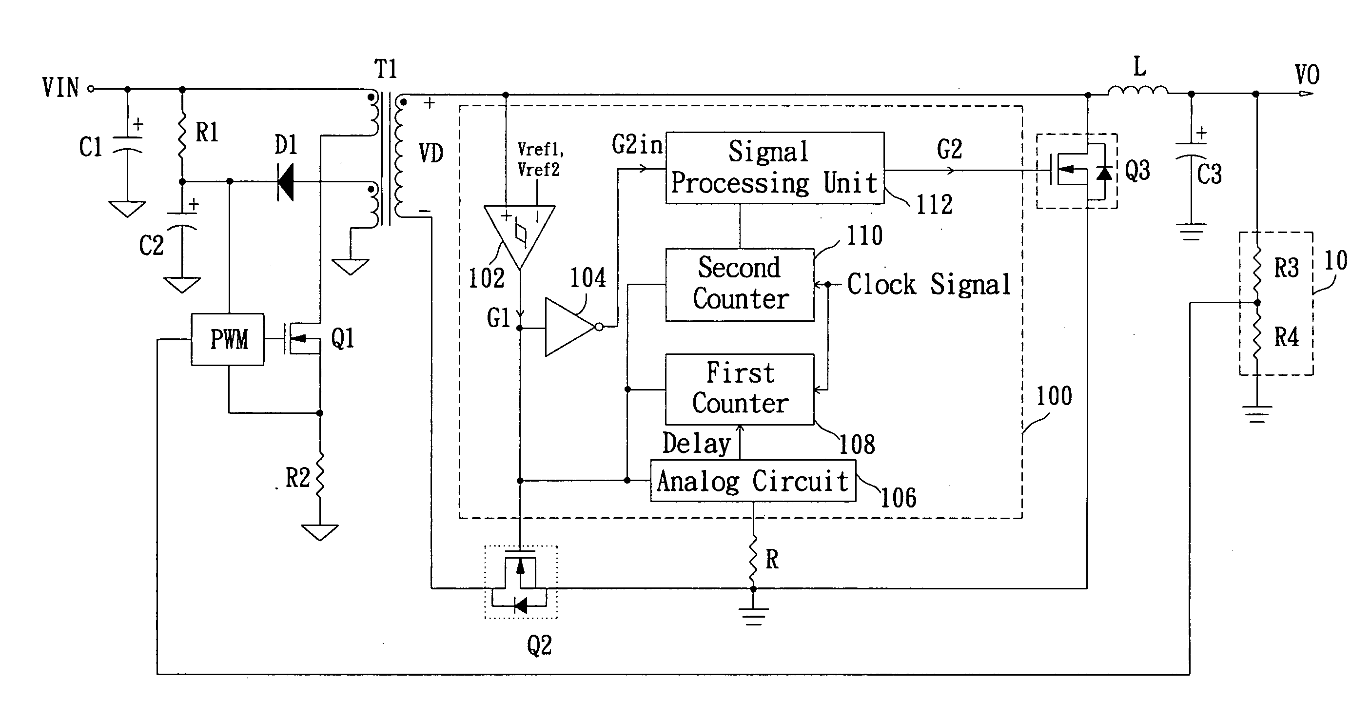
[0022]Refer to FIG. 4, wherein a diagram of forward synchronous rectifier circuit according to a preferred embodiment of the present invention is shown. The depicted forward synchronous rectifier circuit includes an input voltage VIN, a pulse width modulation controller PWM, an input filtering capacitor C1, an start-up resistor R1, an start-up capacitor C2, a current detecting resistor R2, a rectifier diode D1, transistor switches Q1, Q2 and Q3, a transformer T1, an energy storage i...


PUM


Abstract

A synchronous rectifier control device comprises a status detecting unit, an analog circuit, a first counter, a second counter and a signal process unit. The status detecting unit receives at least one reference signal and a detecting signal to generate a first synchronous control signal. The analog circuit generates a delay signal in accordance with the first synchronous control signal. The first counter receives a clock signal and generates a first counter signal in accordance with the first synchronous control signal, the clock signal, and the delay signal. The second counter receives the clock signal and generates a second counter signal in accordance with the first synchronous control signal, the clock signal, and the first counter signal. The signal process unit generates a second synchronous control signal in accordance with the first synchronous control signal and the second signal.

Description

BACKGROUND OF THE INVENTION[0001]1. Field of the Invention[0002]The present invention relates to a forward synchronous rectifier control device and a forward synchronous rectifier circuit; in particular, to a forward synchronous rectifier control device and a forward synchronous rectifier circuit in which deadtime may be set by using an analog circuit.[0003]2. Description of Related Art[0004]FIG. 1 illustrates a diagram of a conventional forward coverter. The forward converter is provided with a transformer T1, and a primary side of the transformer T1 has an input voltage VIN is provided by a pre-stage circuit, a pulse width modulation controller PWM, an input filtering capacitor C1, an start-up resistor R1, an start-up capacitor C2, a current detecting resistor R2, rectifier diode D1 and a transistor switch Q1 controlled by pulse width modulation controller PWM. On the secondary side of transformer T1 has two output rectifier diodes D2, D3, an energy storage inductor L, an output f...

Claims


Application Information

Patent Timeline
Patent Type & Authority Applications(United States)
IPC IPC(8): H02M3/335
CPCY02B70/1475H02M3/33592Y02B70/10
Inventor LIN, CHUN-MINGHSU, TA-CHINGCHU, YUN-KANG
Owner NIKO SEMICON
Features
  • R&D
  • Intellectual Property
  • Life Sciences
  • Materials
  • Tech Scout
  • Unparalleled Data Quality
  • Higher Quality Content
  • 60% Fewer Hallucinations
Learn More