
Integrated flow field plate and diffusion electrode in a fuel cell

a flow field plate and fuel cell technology, applied in the field of fuel cells, can solve the problems of low catalyst activity for methanol electro-oxidation, crossover of methanol through, and dmfcs from widespread commercial applications, so as to reduce the liquid fuel, simplify the manufacturing and assembly of the fuel cell, and reduce the cost

Inactive Publication Date: 2009-07-02
THE HONG KONG UNIV OF SCI & TECH
View PDF11 Cites 21 Cited by
  • Summary
  • Abstract
  • Description
  • Claims
  • Application Information

AI Technical Summary

Benefits of technology

[0015]The present disclosure describes a new electrode module featuring an integrative structure that serves as both a diffusion electrode and a liquid flow field plate. This structure allows a fuel cell system to be fed by a high concentration liquid fuel (e.g. methanol) while reducing the liquid fuel (e.g. methanol) which crosses over to the cathode side. Manufacturing and assembly of the fuel cell can be simplified and costs can be reduced.

Problems solved by technology

So far, two main obstacles prevent DMFCs from widespread commercial applications.
One obstacle is a low catalyst activity for methanol electro-oxidation.
The other obstacle is the crossover of methanol through the polymer electrolyte membrane to the cathode.
It has been realized that methanol crossover not only lowers fuel utilization efficiency but also reduces the output voltage of the methanol / oxygen electrochemical system.
Unavoidably, the “dilution” requirement lowers the reaction rate of methanol oxidation, and thus sacrifices the energy density of a compact DMFC system.
This is particularly deleterious where a physically small fuel cell is desired, such as in portable electronics applications.
While some of these methods have reported data which demonstrates some reduction of methanol crossover, other electrochemical and mechanical properties (e.g. proton conductivity, mechanical strength and cost) of the new membranes are unavoidably compromised.
However, the use of a specialized permeable tube can be costly and difficult to implement, and in any case the methanol consumption problem is in many ways not sufficiently addressed by this concept.
However, the formation and retention of a stable CO2 layer can become a very difficult task, especially during long-term operation.
Instead of using CO2, the approach utilized hydrogel based fuel cartridges as a way to control methanol diffusion flux through the membrane, which consequently improved the DMFC performance at high methanol concentrations, e.g. 8 M. However, the necessity of a hydrogel based fuel cartridge can lead to increased costs and assembly time for the fuel cell.
More generally, even the use of a separate diffusion electrode and liquid flow field plate can lead to increased manufacturing costs and time, and contact resistance therebetween can lead to decreased fuel cell efficiency.

Method used


Image

  • Integrated flow field plate and diffusion electrode in a fuel cell
  • Integrated flow field plate and diffusion electrode in a fuel cell
  • Integrated flow field plate and diffusion electrode in a fuel cell

Examples


example 1

Direct Methanol Fuel Cell (DMFC) with Anodic Integrative Structure

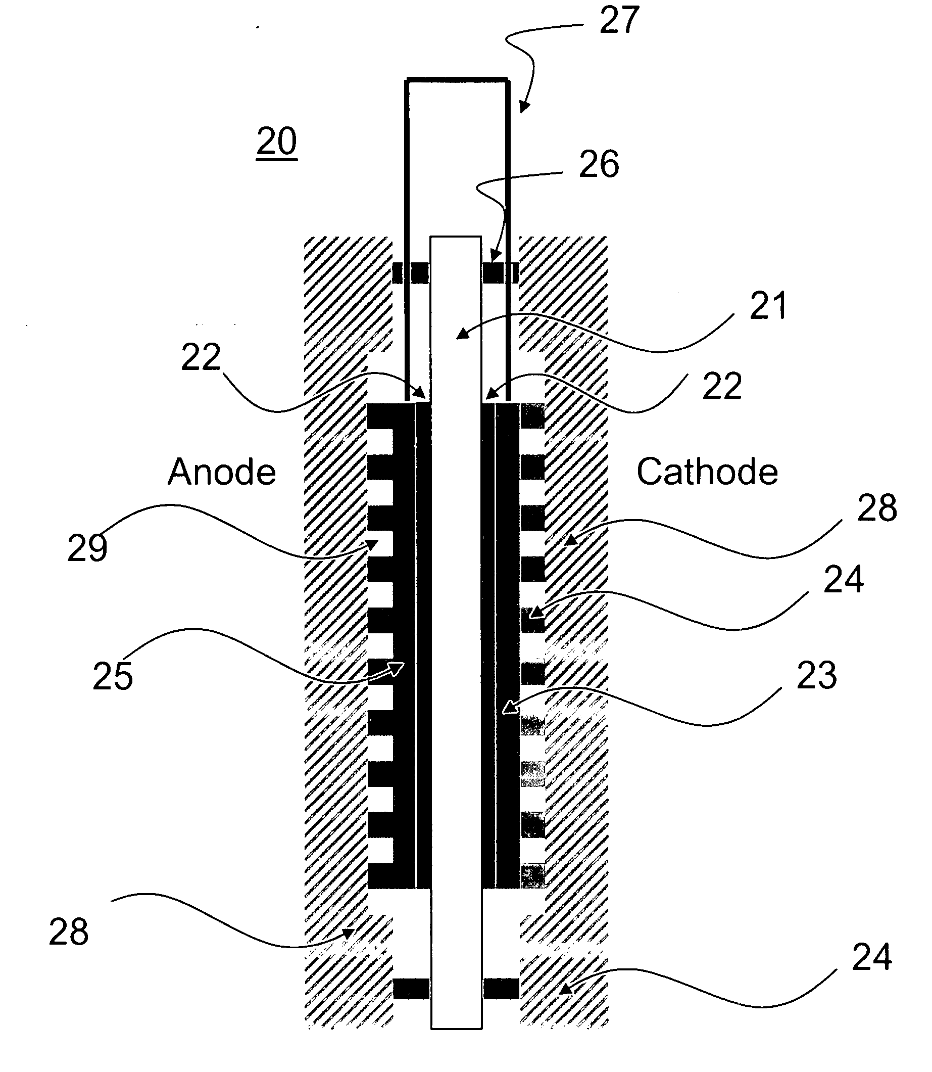
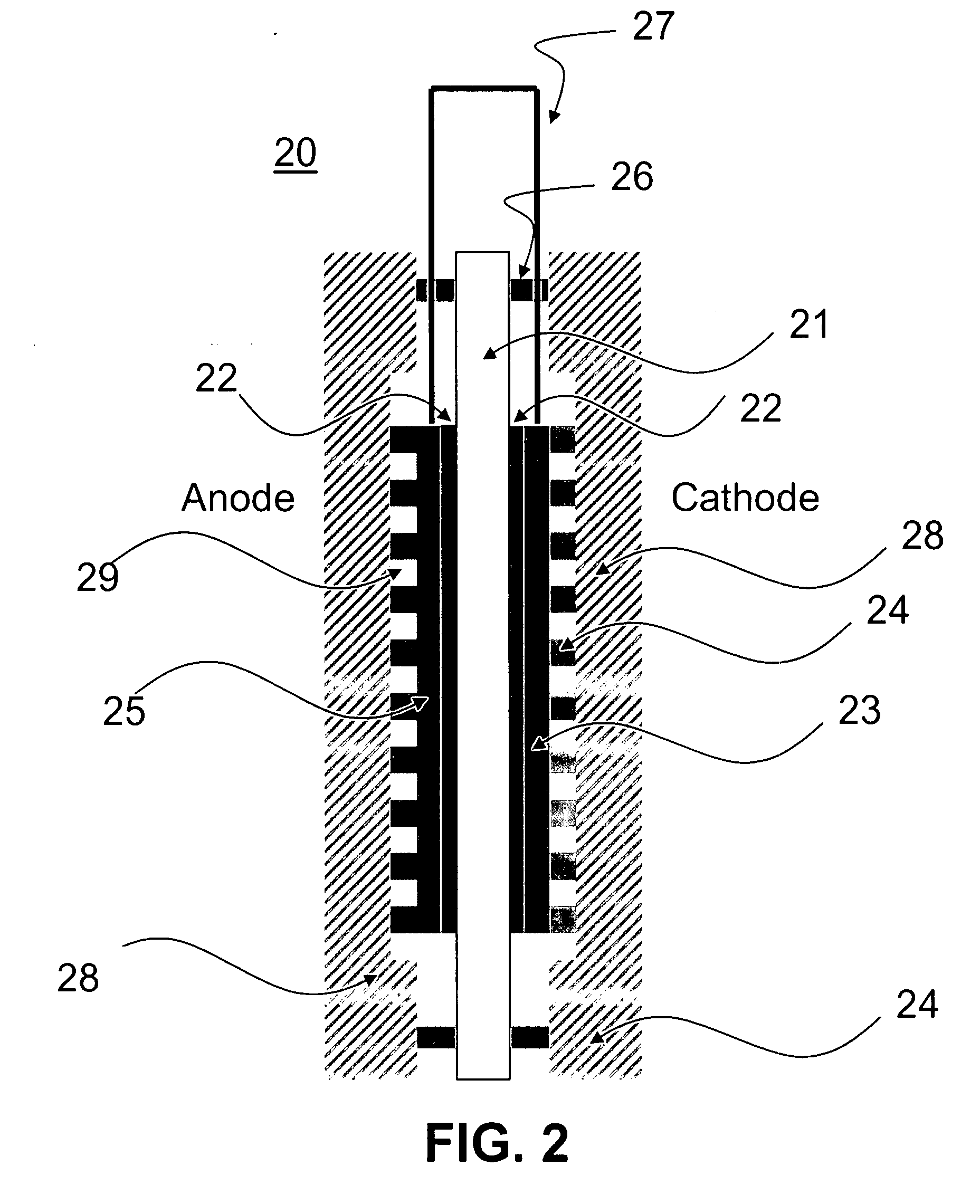
[0054]Again making reference to FIG. 2, in one aspect of the present disclosure, a fuel cell includes an anode 25 made from a flexible graphite plate. In this example, a conventional cathode is used. The flexible graphite plate is mechanically-molded (or otherwise structured) to form a flow field pattern for product and reactant transport. For example, parallel flow field patterns may be mechanically formed in the graphite plate for methanol transport. Methanol solution flows through the channels29 and diffuses through the electrode 25 to the interface between the catalyst 22 and the membrane 21. The diffusion flux of aqueous methanol to the interface can be effectively adjusted to a reasonable level by controlling the structure of electrode 25, such as its porosity. Typical spacing and sizes of parallel flow field patterns for the present disclosure are shown in FIG. 3, where inter-channel spacing is about 1.4 mm, ch...


PUM


Abstract

A fuel cell has at least one electrode having channels for delivering reactants, products, or both. The electrode is an anode or cathode of the fuel cell, or both. The electrode can serve as both a liquid diffusion layer and a flow field plate, thus replacing the traditional elements of carbon paper, cloth diffusion layer, and anode current collector. In some aspects, the fuel cell uses methanol, and the electrode is formed from flexible graphite. The electrode can have a structure sufficient to permit methanol diffusion while preventing methanol crossover. The electrode can also improve volumetric power density and eliminate contact resistance typically present between a conventional flow field plate and conventional diffusion electrode layer.

Description

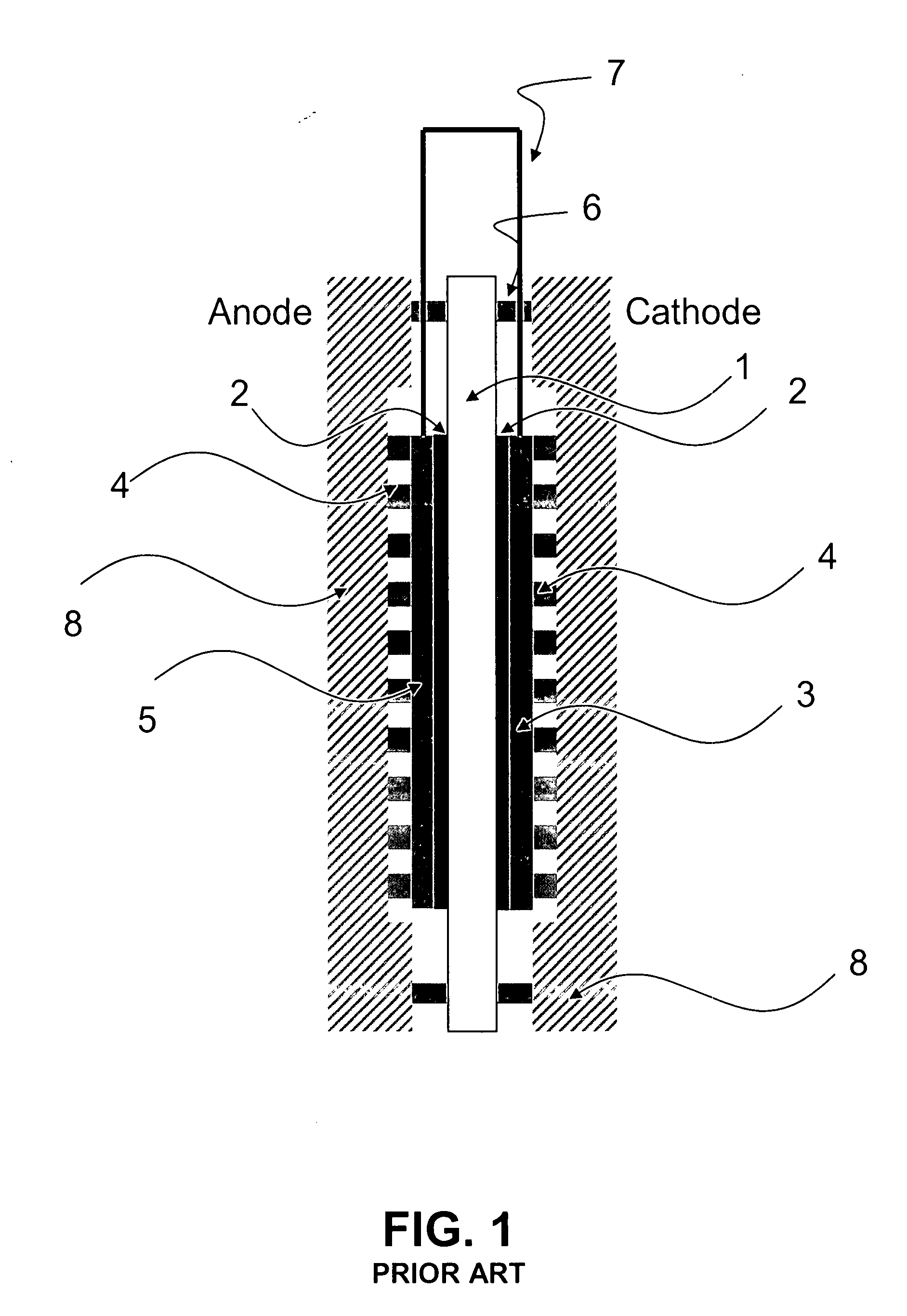
CROSS-REFERENCE TO RELATED APPLICATIONS[0001]This application claims the benefit of U.S. Provisional Patent Application No. 60 / 857,912, filed Nov. 13, 2006, the contents of which are hereby incorporated by reference in their entirety.BACKGROUND OF THE INVENTION[0002]1. Field of the Invention[0003]The present invention relates generally to fuel cells, and more particularly to flow fields and electrode structures of fuel cells and to the control of diffusion rates of reactants in a liquid-feed fuel cell system.[0004]2. Related Art[0005]Fuel cells are promising power sources for their high energy efficiency. A solid polymer fuel cell is a specific type of fuel cell, and can employ a membrane electrode assembly (MEA). As shown in FIG. 1, an MEA comprises a solid electrolyte membrane 1 sandwiched between a cathode 3 and an anode 5, electrically connected by wire 7. Optional catalysts layers 2 can be placed between the anode or cathode and the solid electrolyte membrane. Flow field plates...

Claims


Application Information

Patent Timeline
IPC IPC(8): H01M4/00H01M4/60H01M4/96
CPCH01M4/8605Y02E60/523H01M8/1011H01M4/8626Y02E60/50
Inventor HSING, I MINGZHANG, HAIFENG
Owner THE HONG KONG UNIV OF SCI & TECH
Learn More