Heat exchanger, heat-exchange reformer, and methods of producing heat-exchanger and heat-exchange reformer

a technology of heat exchanger and reformer, which is applied in the direction of sustainable manufacturing/processing, lighting and heating equipment, electrochemical generators, etc., can solve the problems of heat loss, reduce the amount of heat exchange, and heat loss on the face, so as to suppress the heat deformation of the stacked core, reduce local concentration of stress, and simplify the structure

Inactive Publication Date: 2009-07-09
TOYOTA JIDOSHA KK
View PDF5 Cites 6 Cited by
  • Summary
  • Abstract
  • Description
  • Claims
  • Application Information

AI Technical Summary

Benefits of technology

[0010]The heat-insulation layer is formed between the case and the stacked core. This increases resistance to heat transfer from the outer surface of the stacked core to the outside. Therefore, it is possible to suppress heat loss due to heat radiation from the stacked core. For example, when gas such as air is in the closed space, a convection flow of gas is suppressed in the space, particularly by making the closed space flat and narrow. Therefore, a high heat-insulation effect is obtained.
[0026]According to the above-described aspect, the reforming raw material is introduced into the reforming passage (first passage) through the first inlet passage formation portion, and the reforming reaction is caused to generate the hydrogen-containing gas using the reforming raw material in the reforming passage (first passage) while combustion heat generated by burning the fuel is supplied from the heating passage (second passage) to the reforming passage (first passage) (i.e., while heat is transferred from the heating passage to the reforming passage). Because the heat exchanger having each of the above-described structures is used in the heat-exchange reformer, it is possible to effectively reduce the possibility that heat generated in the heating portion is radiated, and is not consumed in the reforming portion, or the heat is radiated from the reforming portion to the outside. This improves the reforming efficiency of the heat-exchange reformer.

Problems solved by technology

This causes heat loss.
This, however, reduces the amount of heat exchange.
This causes heat loss on this faces.

Method used


Image

  • Heat exchanger, heat-exchange reformer, and methods of producing heat-exchanger and heat-exchange reformer
  • Heat exchanger, heat-exchange reformer, and methods of producing heat-exchanger and heat-exchange reformer
  • Heat exchanger, heat-exchange reformer, and methods of producing heat-exchanger and heat-exchange reformer

Examples


first embodiment

[0040]A heat-exchange reformer 10 according to the invention will be described with reference FIG. 1 to FIG. 5. First, the entire configuration of a fuel cell system 11 in which the heat-exchange reformer 10 is employed will be described. Then, the structure of the heat-exchange reformer 10 will be described in detail.

[0041]The entire configuration of the fuel cell system 11 will be described. FIG. 5 shows a configuration diagram (process flow-sheet) of the fuel cell system 11. As shown in FIG. 5, the fuel cell system 11 includes a fuel cell 12 and a reforming unit (reformer) 10. The fuel cell 12 and the reformer 10 are main elements of the fuel cell system 11. The fuel cell 12 consumes hydrogen and generates electric power The reformer 10 generates reformed gas to be supplied to the fuel cell 12. The reformed gas contains hydrogen.

[0042]In the fuel cell 12, an electrolyte (not shown) is provided between an anode electrode (fuel electrode) 14 and a cathode electrode (air electrode) ...

second embodiment

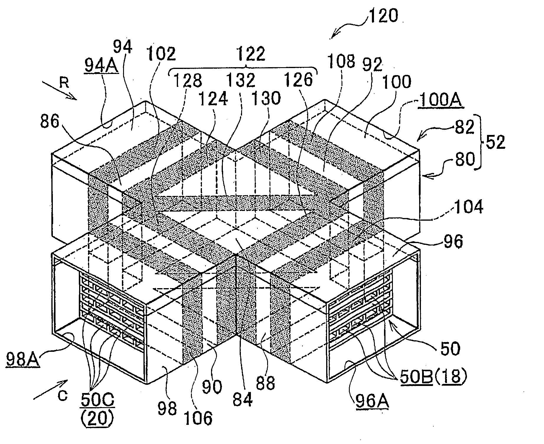
[0091]The other portions of the configuration of the heat-exchange reformer 120 are the same as those of the configuration of the heat-exchange reformer 10.

[0092]Accordingly, in the heat-exchange reformer 120 according to the second embodiment, the same effects are obtained as in the heat-exchange reformer 10 according to the first embodiment. Also, in the heat-exchange reformer 120, the heat-insulation layer 112 is partitioned into a plurality of heat-insulation layers (the first inner heat-insulation layer 140A, the second inner heat-insulation layer 140B, and the four outer heat-insulation layers 142). Therefore, if the degree of vacuum in one of the heat-insulation layers decreases, a convection flow (for example, the convection flow of air that enters the one of the heat-insulation layers) does not occur in the entire heat-insulation layer 112. Thus, a sufficient level of heat-insulation performance is maintained. That is, for example, if the degree of vacuum in one of the out...

third embodiment

[0096]The other portions of the configuration of the heat-exchange reformer 150 are the same as those of the configuration of the heat-exchange reformer 10.

[0097]Accordingly, in the heat-exchange reformer 150 according to the third embodiment, the same effects are obtained as in the heat-exchange reformer 10 according to the first embodiment. In the heat-exchange reformer 150, the manifolds 94, 96, 98, and 102 are formed by joining the manifold members 154, which are separate members, to the case 152. Therefore, there is much flexibility in the design. That is, no restriction is placed on the design of each of the manifolds 94, 96, 98, and 102 by the size and shape of the case 152. Although the open ends 94A, 96A, 98A, and 100A have a rectangular shape in this embodiment, the open ends may have shapes in accordance with, for example, the shapes of the respective lines connected to the open ends (i.e., the shapes of the raw-material supply line 28, the reformed-gas supply line 30, t...


PUM

PropertyMeasurementUnit
temperatureaaaaaaaaaa
shapeaaaaaaaaaa
areaaaaaaaaaaa

Abstract

A heat exchanger includes: a stacked core formed by stacking a plurality of unit plate members in each of which passage formation portions are formed independently of each other to extend from a heat-exchange passage formation portion along a plane; a case formed in accordance with the outer shape of the stacked core, and which houses the stacked core such that heat-exchange media flow into and flow out of the stacked core; and a join portion that serves as a sealing mechanism that supports the stacked core such that the stacked core does not contact the case, and that forms a heat-insulation layer between the case and the stacked core, wherein the heat-insulation layer is a closed space separated from the outside.

Description

BACKGROUND OF THE INVENTION[0001]1. Field of the Invention[0002]The invention relates to a heat exchanger, a heat-exchange reformer in which the heat-exchanger is used, and which generates hydrogen by reforming a raw material, and methods of producing the heat exchanger and the heat-exchange reformer.[0003]2. Description of the Related Art[0004]A cross-flow fuel reformer is available. In the cross-flow fuel reformer, a plurality of plates are stacked. Each of reforming passages is formed between the plates, and each of heating passages is formed between the plates. The reforming passage and the heating passage are adjacent to each other via the plate. In the reforming passage, a hydrocarbon raw material is reformed to generate hydrogen-containing gas. In the heating passage, fuel gas is burned to supply heat to be used for a reforming reaction in the reforming passage. Such a fuel reformer is described, for example, in Japanese Patent Application Publication No. 2004-244230 (JP-A-20...

Claims


Application Information

Patent Timeline
Patent Type & Authority Applications(United States)
IPC IPC(8): F28F3/00B21D53/02
CPCB01J19/0093Y10T29/4935B01J2219/00783B01J2219/00822B01J2219/00824B01J2219/00835B01J2219/00873B01J2219/1923B01J2219/2453B01J2219/2458B01J2219/2465B01J2219/247B01J2219/2479B01J2219/2481B01J2219/2485B01J2219/2486B01J2219/2487B01J2219/2493C01B3/384C01B2203/0233C01B2203/066C01B2203/0811C01B2203/0822C01B2203/0827C01B2203/1223C01B2203/1241C01B2203/1247C01B2203/141F28D9/0037F28D9/02F28F3/048F28F9/005H01M8/0612F28F2230/00B01J19/249F28F2270/00Y02P20/10Y02E60/50
Inventor MITSUI, HIROYUKISHIMAZU, TAKASHIKIMURA, KENJI
Owner TOYOTA JIDOSHA KK
Why Eureka
Try Eureka