[0005]This and other features and objects are provided in accordance with an aspect of the present invention to provide an RFID transponder. The RFID transponder comprises an antenna for receiving data in a downlink mode and transmitting data in an uplink mode. A modulation stage is provided for modulating uplink data, as well as a
demodulation stage for demodulating downlink data. The transponder also includes a class C
amplifier. The class C
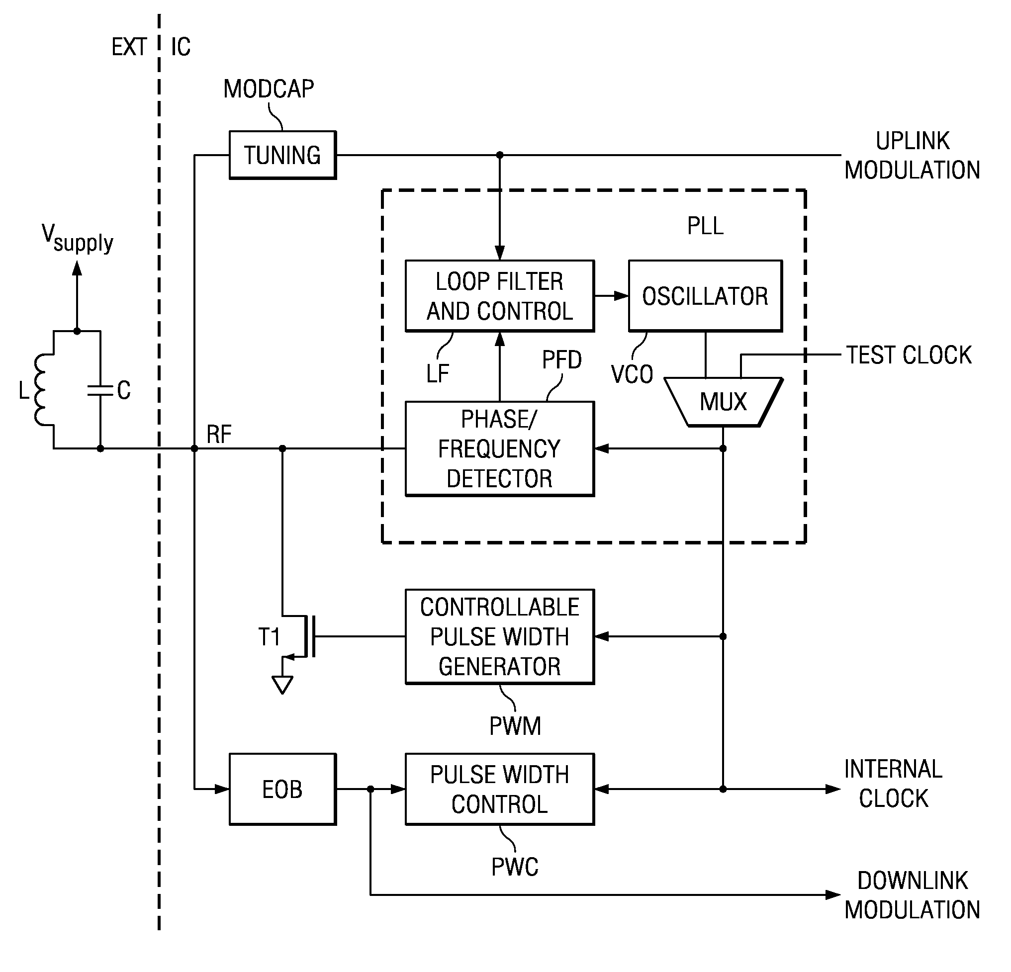
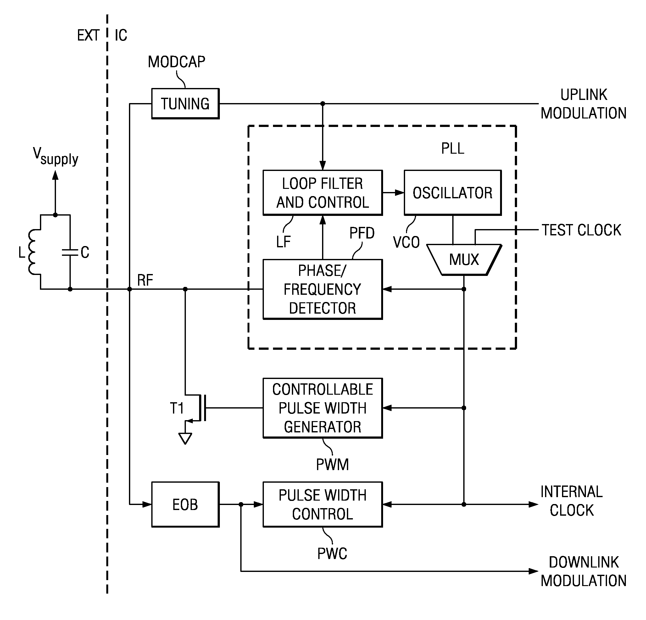
amplifier comprises an resonant circuit (e.g. a LC tank), a plucking device coupled to the resonant circuit, and a controllable pulse width generator coupled to the plucking device. The controllable pulse width generator is connected to an internal oscillator to periodically switch the plucking device on and off so as to maintain an oscillation of the resonant circuit. The antenna and the resonant circuit can comprise the same L, C components, i.e. parts or all of the antenna can constitute the resonant circuit and vice versa. Practically, the antenna and the resonant circuit can be the same. Further, the transponder also comprises a
phase locked loop (PLL) configured to be locked to an RF signal received through the antenna (i.e. the resonant circuit) and to be switched into a free running mode when the PLL is locked to the input RF frequency. The PLL is thereby adapted to output an independent internal
clock signal for the RFID transponder. The resonant circuit is excited by an oscillating RF signal received at the antenna and the PLL, which is coupled to the oscillator (e.g. a
voltage controlled oscillator), is tuned to the external excitation frequency of the received RF signal. Once locked to the external RF frequency received by the antenna, the PLL generates an output signal which can be used as an internal
clock signal for
demodulation and for maintaining oscillation in the resonant circuit (i.e. at the antenna) for uplink. In this case the internal
clock signal generated by the PLL is input to the controllable pulse width generator so that, based on the internal
clock signal, the controllable pulse width generator switches the plucking device, and thus the resonant circuit, on and off with the same frequency as the
clock signal. When the plucking device is switched on, power is induced in the resonant circuit, which compensates for any losses in the resonant circuit and thus allows the oscillation to be maintained by using the internal clock signal generated by the PLL. The controllable pulse width generator is used to control the amplitude in the resonant circuit by using, for instance, the demodulation circuit output signal as an indicator for the output amplitude. In this way, oscillation is able to be maintained, and thus the transponder is able to continuously operate, without the need to use an internal
crystal oscillator. This reduces the cost of the transponder, and increases the circuit space available.
[0006]The modulation stage may comprise means for tuning an oscillating frequency of the resonant circuit (i.e. for example of the antenna) to provide an uplink
frequency shift keying (FSK) signal. To improve efficiency for uplink, means for tuning the (e.g. external) resonant circuit approximately to the frequency of the PLL oscillator can be also provided. The tuning means can be implemented, for example, as a simple tunable
capacitor chosen according to the uplink modulation signal to shift the resonant frequency of the resonant circuit. In order to provide an uplink ASK signal, the output signal of the PLL may be inverted, so as to produce a signal having a 180° phase shift with respect to the signal from the R / W unit. This attenuates the signal in the resonant circuit and thus serves for backscattering modulation. No additional hardware is required.
[0008]A
multiplexer can be provided, which is adapted to switch the internal clock signal between the clock signal output by the
phase locked loop and a test clock signal externally applied to the transponder. For testing of the oscillator, the phase locked loop is disconnected and an external test clock is applied to the controllable pulse width generator instead of the output of the phase locked loop. This allows simple testing of the oscillator, since during certain tests its output signal must be accessible; i.e., not used to be input to the phase locked loop.
[0009]The present invention also provides a method for operating a RFID transponder. The RFID transponder is adapted to receive data in a downlink mode and to transmit data in an uplink mode, the method comprising locking a phase locked loop to an oscillating signal received through an antenna, and switching the phase locked loop into a free running mode without being locked to the oscillating signal received through the antenna, thereby providing an independent internal clock signal for the RFID transponder at an output of the phase locked loop. The received oscillating RF signal is fed to a
phase locked loop circuit and is used to lock the phase locked loop, which then outputs the independent internal clock signal. The internal clock signal can then be used to switch the oscillator in such a way that oscillation of the oscillator is maintained and losses are compensated for. The method of the present invention does not require a separate
crystal oscillator, which reduces costs and saves space in the RFID transponder circuit. The antenna can be a
LC resonant circuit.

