Image processing apparatus

a technology of image processing and image pickup, which is applied in the direction of color signal processing circuit, solid-state device signal generator, picture signal generator, etc., can solve the problems of inability to accurately acquire luminance information and color information of measuring objects, limited dynamic range of image pickup apparatus including ccd (coupled charge device) and cmos (complementary metal oxide semiconductor) sensors, and overexposure total or partial

Active Publication Date: 2009-07-09
ORMON CORP
View PDF15 Cites 16 Cited by
  • Summary
  • Abstract
  • Description
  • Claims
  • Application Information

AI Technical Summary

Benefits of technology

[0024]According to the present invention, the photographing conditions can be properly set, in consideration of the time allowable for each processing. In addition, according to the present invention, the photographing conditions can be properly set, while referring to an actually generated composite image. Further...

Problems solved by technology

Generally, a dynamic range (a gradation range capable of expressing luminance) of an image pickup apparatus including a CCD (Coupled Charged Device) and a CMOS (Complementary Metal Oxide Semiconductor) sensor is limited.
Therefore, when an exposure time at the time of photographing is prolonged, total or partial (overexposure) halation occurs, and luminance information and color information of the measuring object can not be accurately acquired.
Reversely, when the exposure time is shortened, total or partial underexposure occurs, and therefore effective luminance information can not be acquired.
Further, in the measuring object havin...

Method used


Image

  • Image processing apparatus
  • Image processing apparatus
  • Image processing apparatus

Examples


embodiment 1

Overall Apparatus Structure

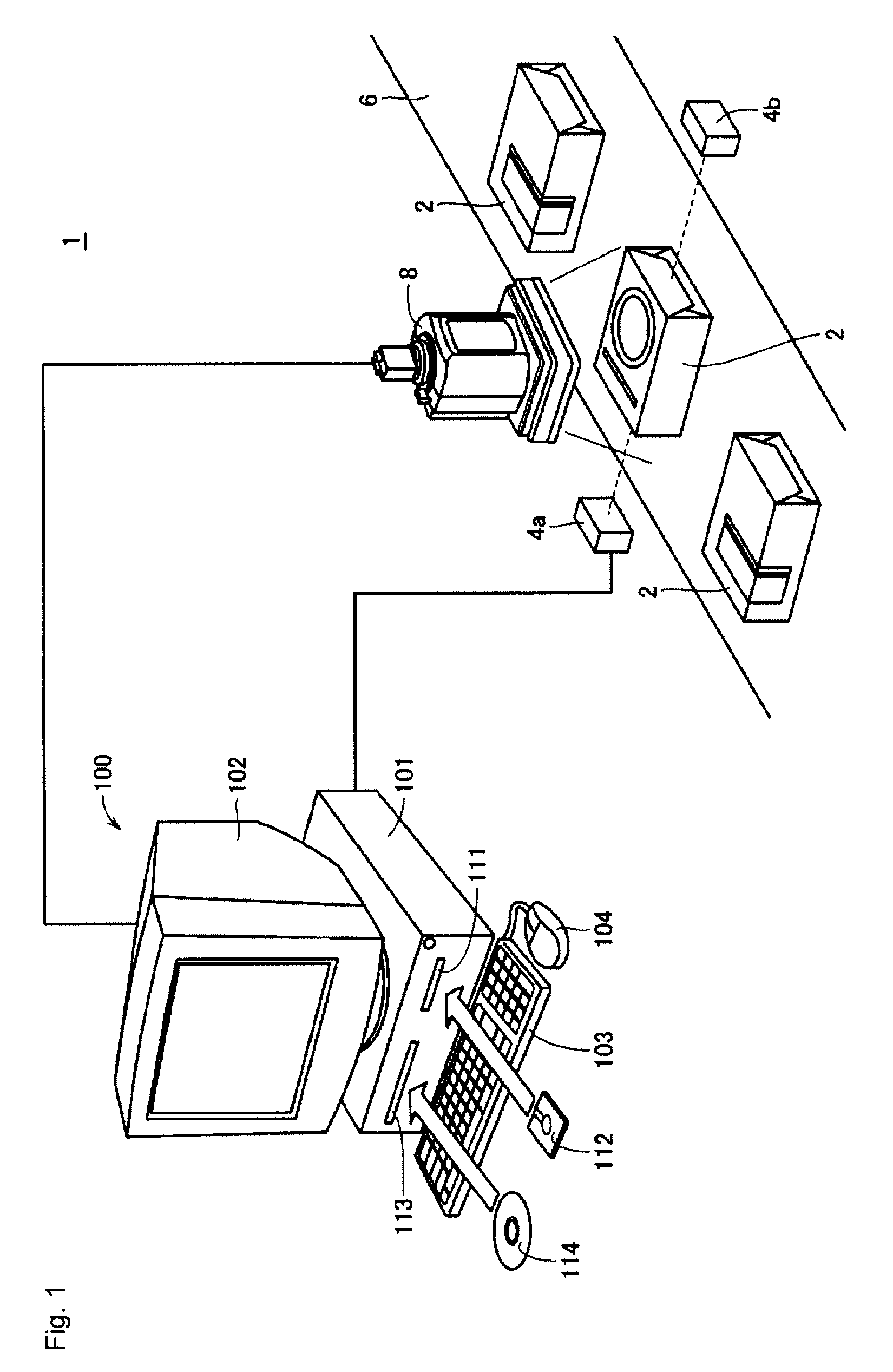
[0047]FIG. 1 shows a schematic view illustrating an overall structure of a visual sensor system 1 including an image processing apparatus according to an embodiment 1 of the present invention.

[0048]In FIG. 1, the visual sensor system 1 is incorporated in a typical production line, and functions to optically inspect a defect, etc, in a measuring object (called a “workpiece” hereafter), and optically measure its size, etc.

[0049]As an example, in the embodiment 1 of the present invention, a workpiece 2 is conveyed by a conveying mechanism 6 such as a belt conveyor, and the conveyed workpiece 2 is sequentially photographed by an image pickup apparatus 8.

[0050]Image data (called “input image data” hereafter) photographed by the image pickup apparatus 8 is transferred to a computer 100 that is a typical example of realizing the image processing apparatus according to this embodiment.

[0051]Note that there may be further provided a lighting mechanism for emitting ...

modified example 1

[0221]The above-described embodiment 1 exemplifies a structure in which an exposure time group is set to be sequentially faster by a power of 2, with “ 1 / 10 seconds” as a reference (slowest value). However, the accuracy of the generated output image data is affected by a change width of this exposure time group (power of 2 in this case), and the length of the processing time is affected thereby. It is preferable to set the change width of this exposure time group further greater or further smaller in some cases, depending on the workpiece. Therefore, the change width of this exposure time group may be made changeable by the user.

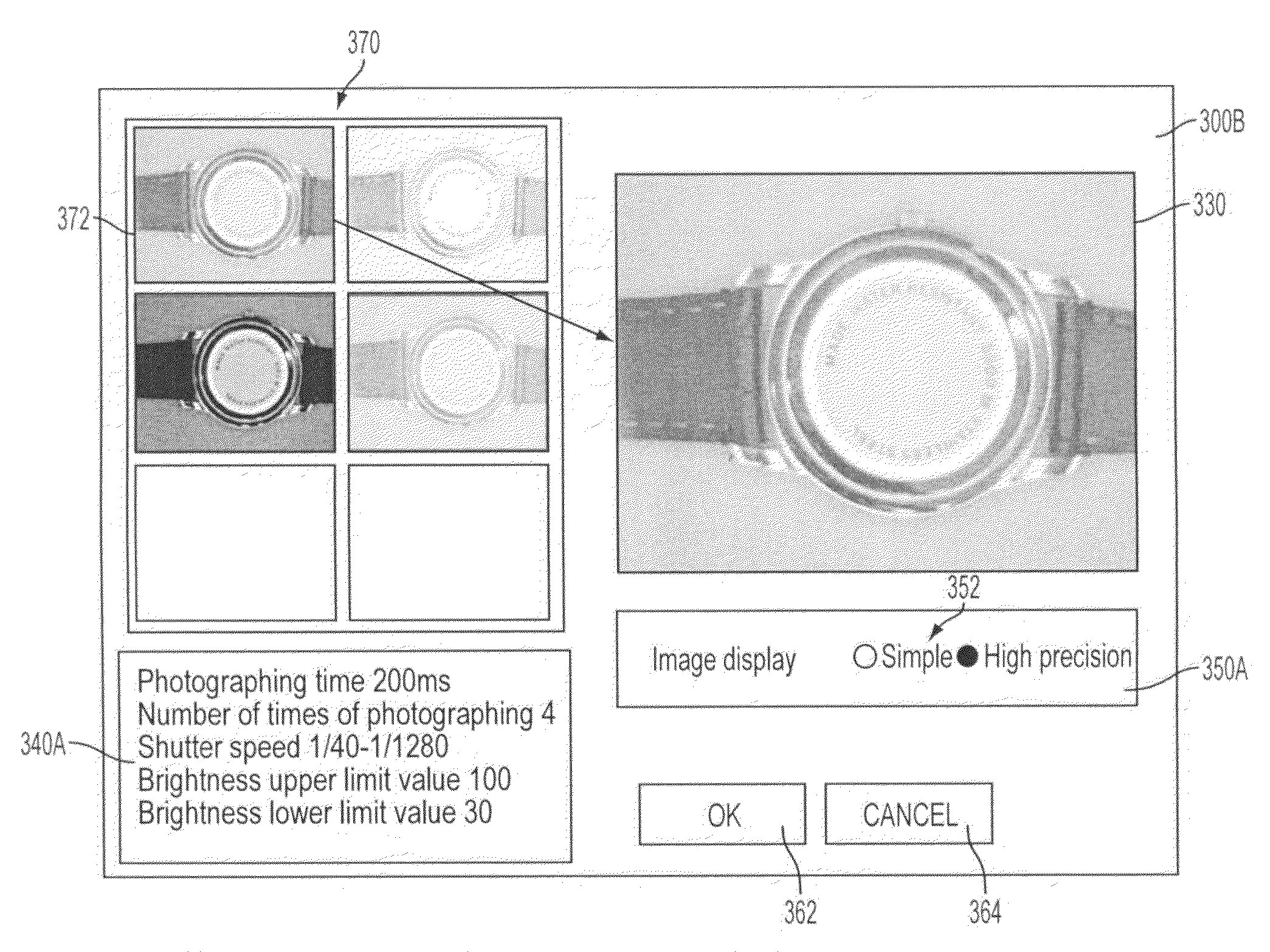
[0222]FIG. 19 shows a view illustrating a screen display example in the “setting mode” displayed on the monitor of the image processing apparatus according to a modified example 1 of the embodiment 1 of the present invention.

[0223]In FIG. 19, the setting mode screen 300A disposes a “brightness” upper / lower limits input area 310A in the setting mode screen 30...

modified example 2

[0225]In the above-described embodiment 1, there is provided a structure as an example, in which the display or non-display of the histogram in the histogram display area 320 can be selected. However, as a method of shortening the processing time and making the update cycle faster, an execution cycle of the generation processing of the histogram having large quantity of information to be processed may be made longer than the execution cycle of the image composition processing. Namely, the operation of changing the “brightness” upper / lower limits setting by the user while referring to the displayed histogram, is relatively slow, and therefore it is not necessary to execute the generation processing of the histogram in the same way as the generation cycle of the composite image.

[0226]Therefore, by constantly performing the operation of the control structure as shown in FIG. 10 and also by performing the operation of the control structure as shown in FIG. 4 at a timing of updating the ...


PUM


Abstract

There is provided an image processing apparatus capable of properly setting a photographing condition in consideration of time allowable for each processing; the image processing apparatus capable of properly setting the photographing condition while referring to an actually generated composite image; the image processing apparatus capable of properly setting the photographing condition even by a user who has no background knowledge; and the image processing apparatus capable of determining whether or not image composition processing is properly executed even by the user who has no background knowledge. A setting mode screen displays a composite image based on generated output image data, together with “processing time”, being expected time required for generating one output image data. The composite image is updated every time the output image data is generated.

Description

[0001]This application claims priority from Japanese patent application P2007-284130, filed on Oct. 31, 2007. The entire content of the aforementioned application is incorporated herein by reference.BACKGROUND OF THE INVENTION[0002]1. Field of the Invention[0003]The present invention relates to an image processing apparatus that processes image data obtained by photographing a measuring object, and particularly relates to a technique of extending a dynamic range by photographing the measuring object a plurality of times under different exposure conditions.[0004]2. Description of the Related Art[0005]In a FA (Factory Automation) field, a so-called visual sensor is put to practical use, as an apparatus for optically inspecting a defect, etc, generated in a measuring object such as a workpiece, and optically measuring a size of this defect.[0006]When an inspection and a measurement are performed by using the aforementioned visual sensor, the measuring object must be properly photograph...

Claims


Application Information

Patent Timeline
IPC IPC(8): H04N9/68
CPCH04N5/23222H04N5/23232H04N9/045H04N5/2351H04N5/2353H04N5/23293H04N23/951H04N23/64H04N23/71H04N23/73
Inventor KATO, YUTAKAKIUCHI, YUTAKA
Owner ORMON CORP
Why Eureka
Try Eureka