Sensor And Method Utilizing Multiple Optical Interferometers

a technology of optical interferometer and sensor, which is applied in the direction of interferometric spectrometry, optical radiation measurement, instruments, etc., can solve the problems of limiting the performance of interferometer, limiting the further reduction of cost, and affecting the further reduction of dimension, so as to achieve enhanced sensitivity and resolution, small size, and low cost

Inactive Publication Date: 2009-07-09
LI CHIAN CHIU
View PDF5 Cites 16 Cited by
  • Summary
  • Abstract
  • Description
  • Claims
  • Application Information

AI Technical Summary

Benefits of technology

[0011]b). to provide such a sensor which has a small size and low cost; and
[0012]c). to provide such a sensor which is able to monit

Problems solved by technology

But because the use of interferometers that employ discrete bulky components, such as focus lens, further dimension reduction is hindered.
Additionally, it is also difficult to reduce the cost further due to the discrete parts.
However, there exists a need for accelerometer that has a smaller size and lower price, especially in the cost-sensitive consumer market.
In reality, however, there are several factors which limit the interferometer performance.
The factors include optical power variation, wavelength shift, and refractive index change, all of which are quite common in practice and expensive to manage.
In other words,

Method used


Image

  • Sensor And Method Utilizing Multiple Optical Interferometers
  • Sensor And Method Utilizing Multiple Optical Interferometers
  • Sensor And Method Utilizing Multiple Optical Interferometers

Examples


Embodiment Construction

—FIGS. 1-A TO 1-C—PRIOR-ART

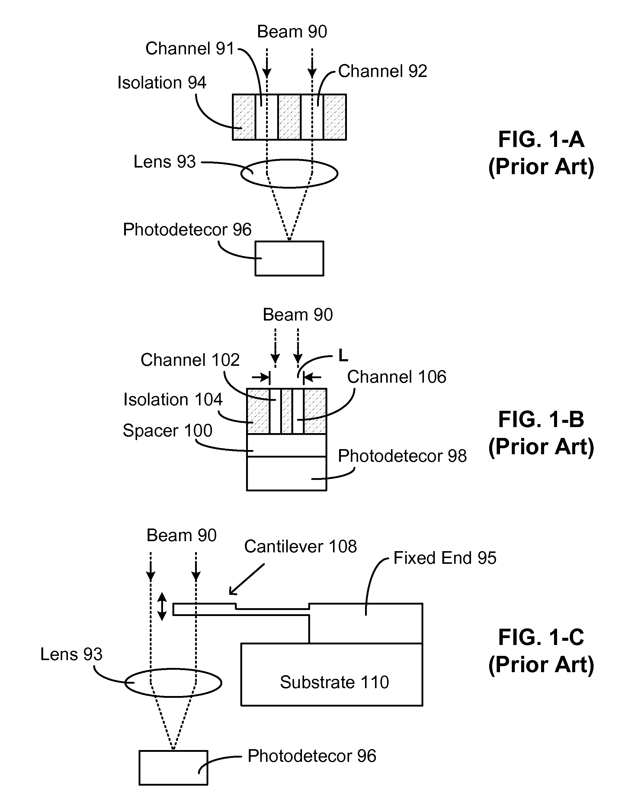
[0027]A prior-art optical interferometer is shown in FIG. 1-A. The interferometer divides an incoming beam 90 into two beam portions by wavefront division. The portions are transmitted through channels 91 and 92 which are surrounded by isolation regions 94 and cause different phase retardation to the portions. After exiting the channels, the portions are mixed by a focus lens 93 to generate interference. A PD 96 is placed behind the lens to measure the interference intensity.

[0028]FIG. 1-B shows a prior-art self-mixing optical interferometer which has a more compact structure than the one of FIG. 1-A. The interferometer has two channels 102 and 106, which split beam 90 into two portions through wavefront division. Isolation regions 104 are made up of materials which stop light propagation. The dimension L, which is addition of the widths of the channels and spacing between them, is small such that when the portions come out of the channels, they merge toge...


PUM


Abstract

Disclosed is a low-cost high-resolution compact accelerometer which utilizes multiple self-mixing optical interferometers. The device is also a micro-opto-electro-mechanical systems (MOEMS) sensor. The interferometers are used to detect acceleration as well as monitor the wavelength, temperature, and refractive index and perform differential measurements. In addition, photodetectors are employed to monitor the input optical power.

Description

CROSS REFERENCE TO RELATED APPLICATION[0001]This application claims the benefit under 35 U.S.C. Sec. 119 of provisional patent application Ser. No. 61 / 018,671, filed Jan. 3, 2008. This application is also related to U.S. application Ser. No.11 / 307,319, filed 1 Feb. 2006, and entitled “Interferometric MOEMS Sensor” and application Ser. No. 11 / 768,265, filed 26 Jun. 2007, and entitled “Optical Interferometer And Method.”FEDERALLY SPONSORED RESEARCH[0002]Not applicableSEQUENCE LISTING OR PROGRAM[0003]Not applicableBACKGROUND[0004]1. Field of Invention[0005]This invention relates to sensors utilizing optical interferometer, and particularly to high-resolution sensors utilizing multiple optical interferometers.[0006]2. Description of Prior Art[0007]Previously disclosed interferometric accelerometers can be made compact thanks to the technology of micro-electro-mechanical systems (MEMS) or micro-opto-electro-mechanical systems (MOEMS). But because the use of interferometers that employ di...

Claims


Application Information

Patent Timeline
IPC IPC(8): G01N21/45G01J3/45G01B9/02
CPCG01J1/0214G01J9/0246G01J2005/583G01K11/00G01B9/02072G01B9/02051G01B9/02027G01B9/02092G01B2290/45G01P15/093G01P2015/0828
Inventor LI, CHIAN CHIU
Owner LI CHIAN CHIU
Why Eureka
Try Eureka