Electrodes for Lanthanum Gallate Electrolyte-Based Electrochemical Systems

a technology of electrochemical cells and lanthanum gallate, which is applied in the field of electrochemical cells, can solve the problems of reducing operating temperatures below 800° c., the incompatibility of nickel-based anodes with lsgm electrolytes is well known, and the development of anode materials and cell fabrication processes still needs to be addressed, so as to reduce the reactivity of nickel

Inactive Publication Date: 2009-07-16
CERAMTEC
View PDF13 Cites 11 Cited by
  • Summary
  • Abstract
  • Description
  • Claims
  • Application Information

AI Technical Summary

Benefits of technology

[0015]In yet another aspect of the invention, an electrochemical cell in accordance with the invention includes a lanthanum gallate electrolyte having a dense layer and a porous layer coupled together. A solid solution of nickel oxide and an oxide, such as magnesium oxide, copper oxide, or copper magnesium oxide, is infiltrated into the porous layer. The oxide reduces the reactivity of the nickel with the lanthanum gallate electrolyte.

Problems solved by technology

Reducing operating temperatures below 800° C. has posed a considerable challenge due to the increased losses that occur at the cathode / electrolyte interface.
However, various challenges in the development of anode materials and cell fabrication processes still need to be addressed to effectively make use of LSGM electrolytes.
However, the incompatibility of nickel-based anodes with LSGM electrolytes is well known.
Specifically, an undesirable interfacial reaction occurs when nickel from the anode diffuses into the LSGM electrolyte, where it reacts to form LaNiO3.
This reaction product has reduced conductivity and significantly degrades SOFC performance.
Although a ceria interlayer between the nickel anode and the LS GM electrolyte appears to improve initial performance as well as extend cell life, a catastrophic drop in cell performance has been shown to occur at about 1,200 hours of operation.
While an obvious explanation is that the ceria interlayer does not entirely prevent nickel diffusion into the electrolyte, it may also be possible that the ceria / LSGM interface itself is not conducive to long-term stability.

Method used


Image

  • Electrodes for Lanthanum Gallate Electrolyte-Based Electrochemical Systems
  • Electrodes for Lanthanum Gallate Electrolyte-Based Electrochemical Systems
  • Electrodes for Lanthanum Gallate Electrolyte-Based Electrochemical Systems

Examples


Embodiment Construction

[0030]It will be readily understood that the components of the present invention, as generally described and illustrated in the Figures herein, could be arranged and designed in a wide variety of different configurations. Thus, the following more detailed description of the embodiments of the invention, as represented in the Figures, is not intended to limit the scope of the invention, as claimed, but is merely representative of certain examples of presently contemplated embodiments in accordance with the invention. The presently described embodiments will be best understood by reference to the drawings, wherein like parts are designated by like numerals throughout.

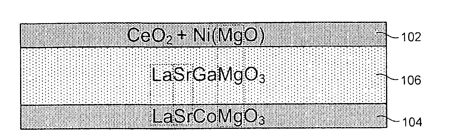
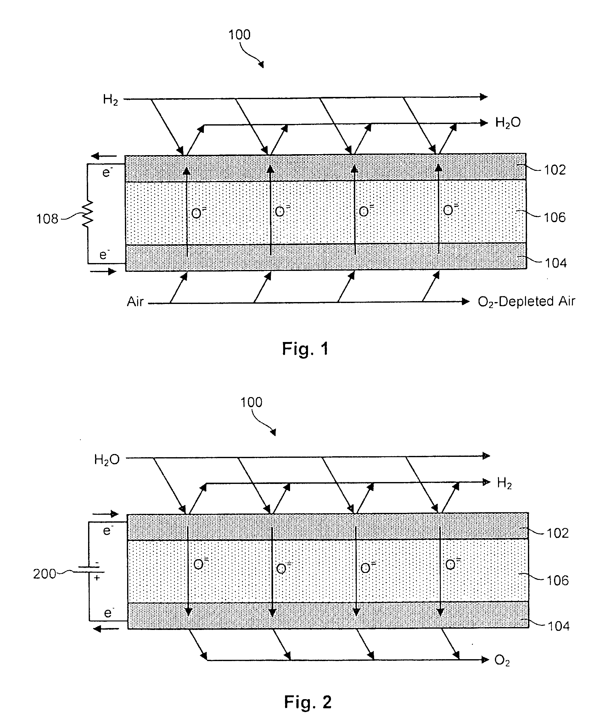
[0031]Referring to FIGS. 1 and 2, in selected embodiments, a solid oxide electrochemical cell 100 in accordance with the invention may include a hydrogen electrode 102, an oxygen electrode 104, and an electrolyte layer 106. Each of the layers 102, 104, 106 may, in certain embodiments, be composed of solid-state materials....


PUM

PropertyMeasurementUnit
temperatureaaaaaaaaaa
operating temperaturesaaaaaaaaaa
electrical conductivityaaaaaaaaaa

Abstract

An electrochemical cell is disclosed in one embodiment of the invention as including an oxygen electrode and a solid oxide electrolyte coupled to the oxygen electrode to transport oxygen ions. A hydrogen electrode is coupled to the solid oxide electrolyte and contains nickel combined with a material tending to reduce the reactivity of the nickel with the solid oxide electrolyte. In selected embodiments, the solid oxide electrolyte is lanthanum gallate. Similarly, the material combined with the nickel may be an oxide such as magnesium oxide.

Description

RELATED APPLICATIONS[0001]This application claims priority to U.S. Provisional Patent No. 60 / 869,709 filed on Dec. 12, 2006 and entitled ELECTRODES FOR LANTHANUM GALLATE ELECTROLYTE-BASED ELECTROCHEMICAL SYSTEMS.BACKGROUND OF THE INVENTION[0002]1. Field of the Invention[0003]This invention relates to electrochemical cells and more particularly to electrodes for lanthanum gallate electrolyte-based electrochemical cells.[0004]2. Description of the Related Art[0005]The benefits of lowering the operating temperature of solid oxide fuel cells (SOFCs) are well recognized. Some of these benefits include: improvement in long-term stability by slowing physical and chemical changes in the cell materials, lower cost systems due to the ability to use smaller heat exchangers made from low cost materials, compatibility with hydrocarbon reformation processes allowing partial internal reformation which further reduces the heat exchanger duty, and finally the potential to improve thermal cycle capab...

Claims


Application Information

Patent Timeline
Patent Type & Authority Applications(United States)
IPC IPC(8): H01M8/10H01M4/00H01M8/14
CPCC01G15/006C01P2002/72H01M4/8885H01M4/9016Y02E60/525H01M8/1246H01M2300/0074Y02E60/521H01M4/9066Y02E60/50Y02P70/50
Inventor ELANGOVAN, S.HARTVIGSEN, JOSEPH J.
Owner CERAMTEC
Why Eureka
Try Eureka