Positive electrode current collector for lead accumulator

a current collector and lead accumulator technology, applied in the direction of non-aqueous electrolyte accumulator electrodes, cell components, electrical apparatus, etc., can solve the problems of deteriorating life performance of lead-acid batteries using current collector substrates, inferior etc., to improve the conductivity of coating, improve the life performance of lead-acid batteries, and high conductivity

Inactive Publication Date: 2009-07-16
GS YUASA INT LTD
View PDF2 Cites 9 Cited by
  • Summary
  • Abstract
  • Description
  • Claims
  • Application Information

AI Technical Summary

Benefits of technology

[0034]In execution of the production method, it is preferable for the raw material solution to contain antimony or fluorine. Existence of antimony or fluorine in the coating improves the conductivity of the coating. In the case where the coating has high conductivity, since the inner resistance of the lead-acid battery is lowered, the life performance of the lead-acid battery becomes further excellent. In the case of comparison of antimony with fluorine, antimony is better.
[0035]The lead-acid battery of the present invention is characterized in that the battery is provided with the above-mentioned positive electrode current collector. Accordingly, since the life performance of the positive electrode current collector is heightened, the lead-acid battery with high energy density and a long life can be provided in a low cost.
[0036]As described above, in the case where a lead-acid battery is produced using a positive electrode current collector according to the present invention, the life performance of the lead-acid battery becomes excellent.

Problems solved by technology

However, in the case where a lead-acid battery is produced using a current collector substrate of titanium or the like having a coating of tin dioxide on the surface, there is a problem that the life performance of the lead-acid battery is inferior.
Accordingly, the life performance of a lead-acid battery using the current collector substrate deteriorates.

Method used


Image

  • Positive electrode current collector for lead accumulator
  • Positive electrode current collector for lead accumulator
  • Positive electrode current collector for lead accumulator

Examples


first embodiment

(1) First Embodiment

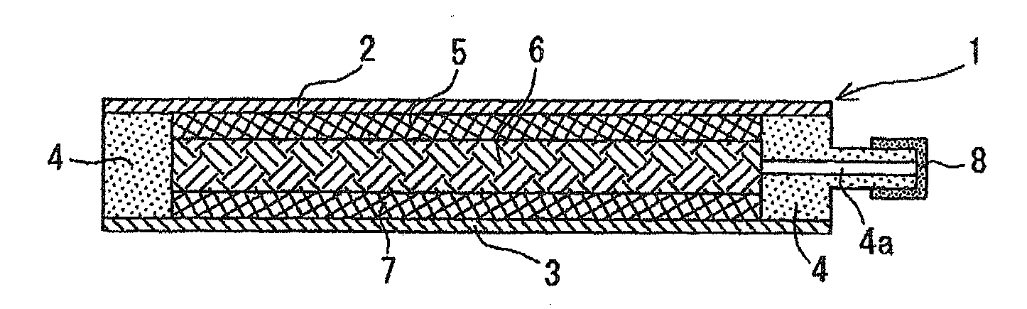
(1.1) Production of Positive Electrode Current Collector

[0046]In Example 1, a mixed solution of a dibutyltin diacetate solution (solvent: ethanol) and an antimony chloride solution (solvent: ethanol) was used as a raw material solution. In this case, the amount of dibutyltin diacetate was adjusted to be 2.5% by mass on the basis of tin dioxide in the entire raw material solution. Further, the amount of antimony chloride was adjusted to be 2.5% by mass on the basis of antimony to tin dioxide.

[0047]The raw material solution was intermittently sprayed to the surface of a flat plate-like current collector substrate heated to 450° C. At the time of spraying, the spraying intervals were controlled so as to keep the temperature of the current collector substrate at 450° C. Accordingly, thermal decomposition is caused on the surface of the current collector substrate to form a coating of tin dioxide. The obtained substrate was set as a positive electrode current collecto...

second embodiment

(2) Second Embodiment

(2.1) Production of Positive Electrode Current Collector

[0078]Positive electrode current collectors were produced while changing the heating temperature of the current collector substrates when the raw material solution was intermittently sprayed to 300° C., 350° C., 380° C., 400° C., 420° C., 450° C., or 450° C. At the time of spraying, the heating temperature was prevented from lowering. The raw material solution to be used was the same raw material solution as in the above-mentioned first embodiment.

[0079]The case where the heating temperature of the current collector substrate was 300° C. was set to be Comparative Example 1; the case of 350° C. was set to be Comparative Example 2; the case of 380° C. was set to be Comparative Example 3; the case of 400° C. was set to be Example 2-1; the case of 420° C. was set to be Example 2-2; the case of 450° C. was set to be Example 2-3; and the case of 500° C. was set to be Example 2-4.

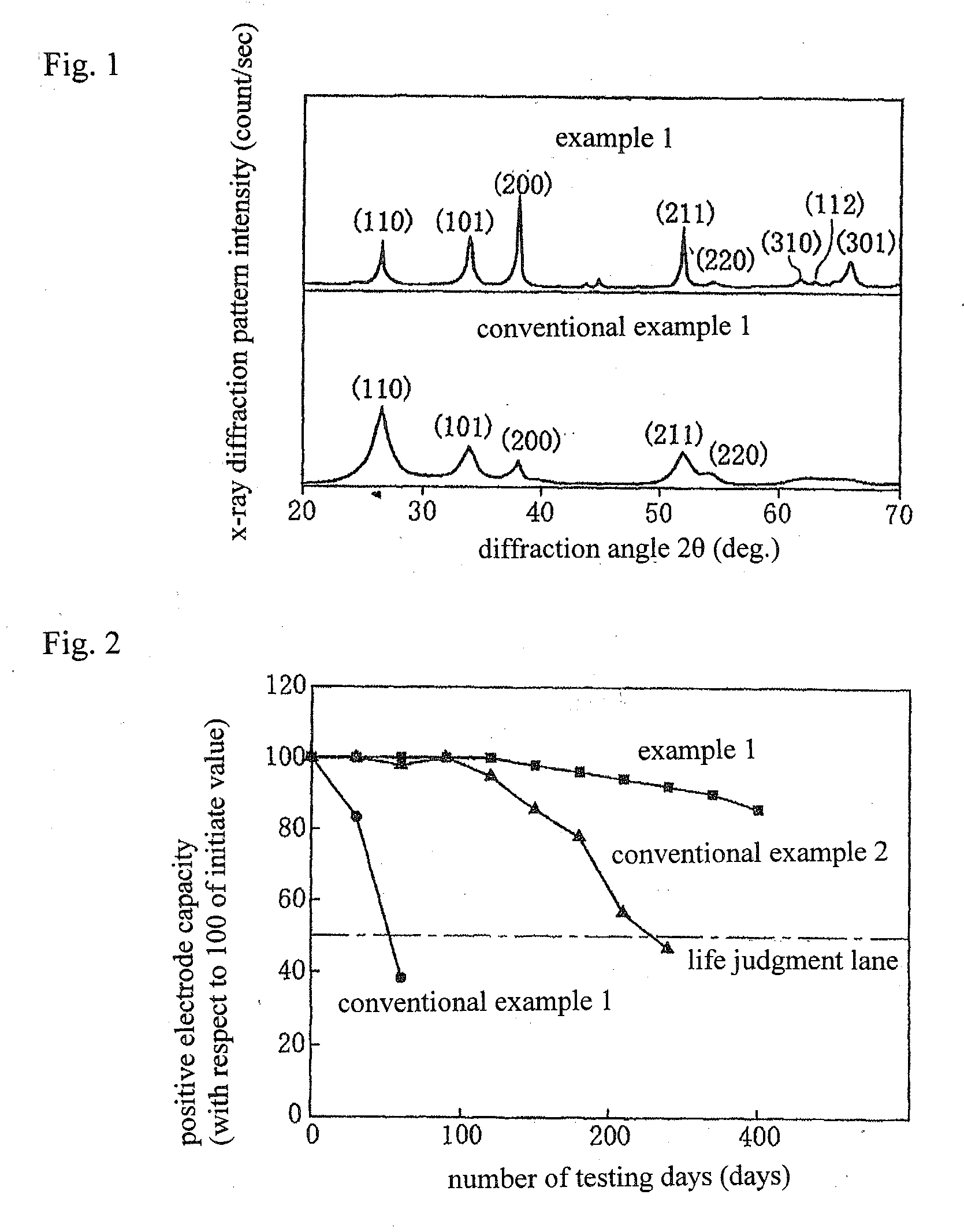
(2.2) Results of X-Ray Diffractome...

third embodiment

(3) Third Embodiment

[0089]In a third embodiment, how the number of selectively oriented crystal planes affected the life performance of the lead-acid battery was investigated.

(3.1) Production of Positive Electrode Current Collector

[0090]The spraying amount of the raw material solution per one time in the production process affects the number of the selectively oriented crystal planes. Further, whether annealing treatment is carried out or not for titanium to which spraying is carried out also affects the number of the selectively oriented crystal planes. Therefore, titanium which was not annealed and titanium which was annealed were used to produce positive electrode current collectors. The spraying amount of the raw material solution per one time was variously changed. Hereinafter, specific explanation will be given.

[0091]Using titanium which was not annealed as a current collector substrate, the raw material solution was intermittently sprayed. In the case of spraying, the sprayin...


PUM

PropertyMeasurementUnit
melting pointaaaaaaaaaa
aaaaaaaaaa
temperatureaaaaaaaaaa

Abstract

In a positive electrode current collector for a lead-acid battery including a coating of tin dioxide formed on the surface of a current collector substrate of titanium or a titanium alloy, the half width of a peak with the maximum intensity among peaks of tin dioxide in the x-ray diffraction pattern of the positive electrode current collector for a lead-acid battery is 1° or lower.

Description

BACKGROUND OF THE INVENTION[0001]1. Field of the Invention[0002]The present invention relates to a positive electrode current collector for a lead-acid battery having a coating on the surface.[0003]2. Description of the Related Art[0004]A lead-acid battery has a low energy density as compared with a nickel-metal hydride battery and a lithium ion battery. One of the causes is that lead or a lead alloy to be used as a positive electrode current collector is thick and heavy. Therefore, use of titanium or a titanium alloy (hereinafter, referred to as titanium or the like) for the positive electrode current collector and formation of a conductive oxide layer of tin dioxide or the like as a coating on the surface of titanium or the like have been proposed (reference to Japanese Patent Application Laid-Open (JP-A) No. 55-64377 and Japanese Patent No. 3482605). It is because use of titanium or the like makes a positive electrode current collector lightweight because of the lower specific gr...

Claims


Application Information

Patent Timeline
Patent Type & Authority Applications(United States)
IPC IPC(8): H01M4/56H01M4/58
CPCH01M4/66H01M4/662H01M4/667Y10T29/49115H01M4/82Y10T29/10H01M4/68Y02E60/10
Inventor KURISAWA, ISAMU
Owner GS YUASA INT LTD
Why Eureka
Try Eureka