UV and Visible Laser Systems

a laser system and visible light technology, applied in the field of solid-state lasers, can solve the problems of poor beam quality, high cost of lasers, and limited choice of shorter wavelength light sources (e.g., visible or uv), and achieve the effect of higher optical frequency

Inactive Publication Date: 2009-07-23
CORNING INC
View PDF2 Cites 53 Cited by
  • Summary
  • Abstract
  • Description
  • Claims
  • Application Information

AI Technical Summary

Benefits of technology

[0011]One aspect of the invention is a laser system comprising: (i) a light source generating light, said light source comprising at least two laser sources of different wavelengths; and (ii) a frequency converter operatively coupled to said light source to accept the light pr

Problems solved by technology

However, in contrast to the widely available light sources developed for the near-IR spectral ranges, the choice of the shorter wavelength light sources (e.g., visible or UV) is very limited.
However, these lasers are expensive, costly to maintain, have relatively poor beam quality, and are not tunable.
Unfortunately, only a few discrete wavelengths are available from DPSS lasers, and therefore, the output wavelengths that are produced by this method are also limited to harmonics (e.g., 2nd, 3rd, 4th) of the fundamental or pump wavelengths.
This is not always possible.
Furthermore, because the output wavelength from OPO is determined by phase matching c

Method used


Image

  • UV and Visible Laser Systems
  • UV and Visible Laser Systems
  • UV and Visible Laser Systems

Examples


example 1

Laser system I for Producing an Output at λ=193.0 nm

[0031]Sub-200 nm laser light sources are very important for metrology applications in the semi-conductor industry. As the feature sizes of integrated circuits are shrinking, shorter wave-length light is used for a photolithography. Mask and wafer inspection, as well as optics manufacturing is then in need of the same or similar DUV light wavelength. The systems presently used, based on solid-state laser sources, harmonic conversion and OPOs, typically work at very low repetition rates, are very bulky, complex, expensive and require frequent and complicated maintenance.

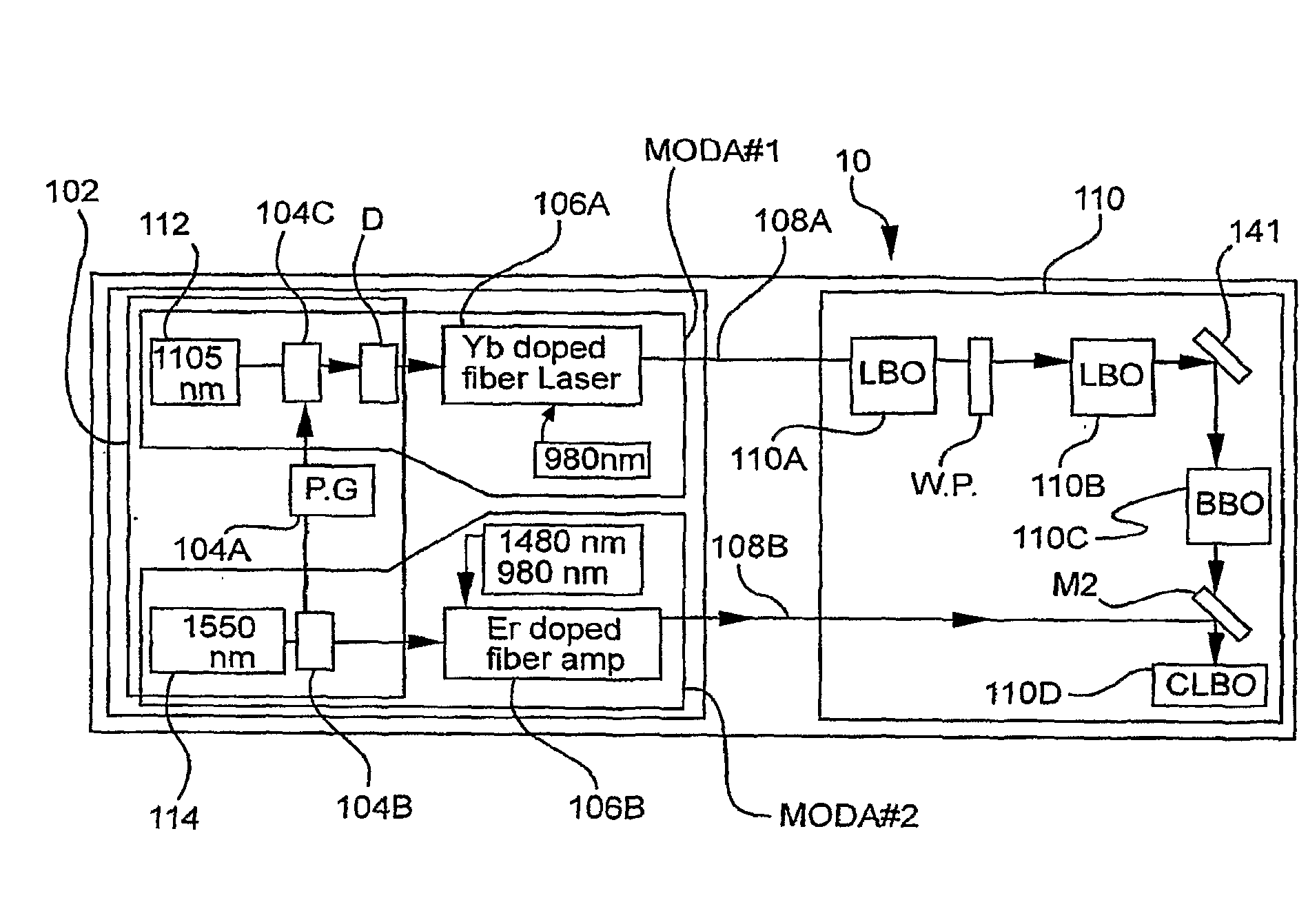
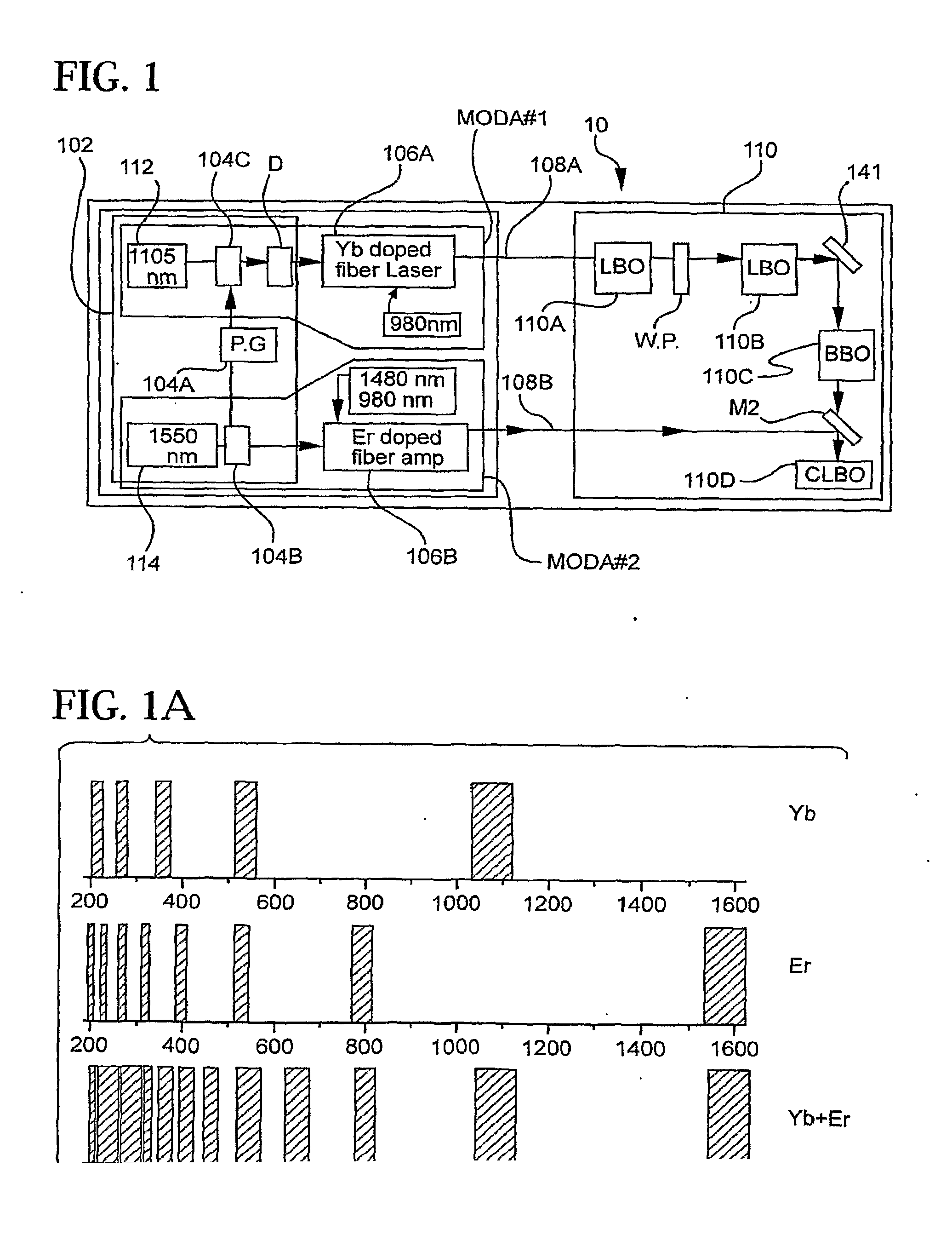
[0032]FIG. 1 illustrates schematically the first exemplary embodiment of the 193.0 nm laser system 10. As described above, the optical system 10, according to this embodiment, includes two optical fiber amplifiers 106A, 106B that provide synchronized pulse outputs of different wavelengths to the frequency converter 110. In this exemplary embodiment, the Yb-doped fiber...

example 2

Laser System for Producing an Output at λ=193.4

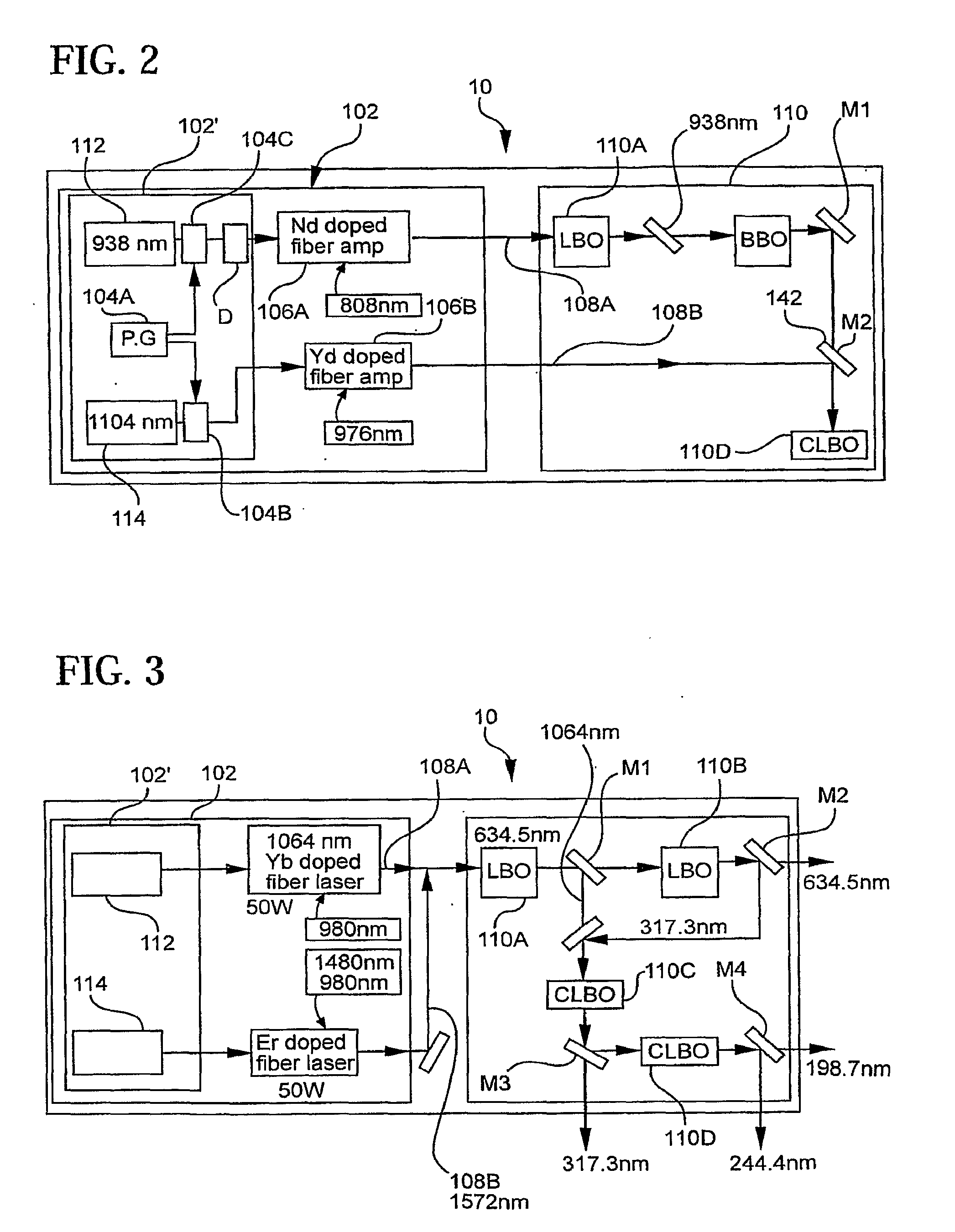
[0037]FIG. 2 presents an example of a 193.0 nm laser system 10 according to another embodiment of the present invention. The laser system 10 of this embodiment is similar to that of the embodiment of example 1 in that it includes a pulsed light source 102 comprising two seeded high power optical amplifiers 106A, 106B that (in parallel) provide synchronized first pulsed light 108A, 108B to the frequency converter 110. However, in this embodiment the first amplifier 106A is Nd-doped (SiO2 based) fiber amplifier. More specifically, the 935.6 nm output of Nd-doped amplifier 106A is provided to the first stage 110A. (LBO crystal) of the frequency converter 110. The 1104 nm output of Yb-doped fiber amplifier 106B is simultaneously provided to the CLBO crystal (3rd stage 110C of the frequency converter 110). The frequency converter 110 includes one LBO crystal 110A, one BBO crystal 110B and one CLBO crystal 110C. The three nonlinear crystals, ...

example 3

Laser System for Producing an Output at λ=198.7 nm

[0043]FIG. 3 illustrates schematically the exemplary embodiment of the 198.7 nm laser system 10. As described above, the optical system 10 according to this embodiment, includes two seeded optical fiber amplifiers 106A, 106B that provide synchronized pulsed outputs of different wavelengths to the frequency converter 110. In this exemplary embodiment, the 1064 nm seeded Yb-doped fiber amplifier 106A of the light source 102, produces a narrow linewidth output at the wavelength λ1Aout=1064 nm. Seeded Er-doped fiber amplifier 106B simultaneously produces light 108B at a narrow linewidth output at wavelength λ2Aout=1572 nm. The 1164 nm and 1572 nm light from the amplifiers 106A, 106B is then provided to the first stage of the frequency converter 110. In this embodiment, the frequency converter 110 includes two LBO crystals 111A, 110B, and two CLBO crystals 110C, 110D. The first stage of the frequency converter 110 corresponds to the LBO c...


PUM


Abstract

A laser system comprising: a light source generating light, said light source comprising at least two laser sources of different wavelengths; and a frequency converter operatively coupled to said light source to accept the light provided by said light source and to convert it to higher optical frequency such that said frequency converter is producing light output at the final output wavelength situated in the 150-775 nm range.

Description

[0001]This application claims the benefit of U.S. Provisional Application No. 60 / 810,505, filed Jun. 2, 2006, entitled “UV and Visible Laser Systems.”BACKGROUND OF THE INVENTION[0002]1. Field of the Invention[0003]The present invention relates generally to solid state lasers and more particularly to laser systems using fiber lasers and nonlinear wavelength conversion to produce output in the ultra violet (UV) and / or visible wavelength ranges.[0004]2. Technical Background[0005]Coherent light sources in the visible (400-775 nm) wavelength range and in the UV or deep UV (DUV) range (150-400 nm) find a number of important applications (such as in medicine, life sciences material processing, photolithography and metrology). Typically, a high output power is desired and different output wavelengths are required for different applications.[0006]However, in contrast to the widely available light sources developed for the near-IR spectral ranges, the choice of the shorter wavelength light so...

Claims


Application Information

Patent Timeline
IPC IPC(8): H01S3/30
CPCG02F1/3532G03F7/70025H01S3/005H01S3/06754H01S3/0092H01S3/1611H01S3/1618H01S3/2383H01S3/1608
Inventor KUKSENKOV, DMITRI VLADISLAVOVICHSUDARSHANAM, VENKATAPURAM SRIRAMANZENTENO, LUIS ALBERTO
Owner CORNING INC
Why Eureka
Try Eureka