Sensorless control apparatus of synchronous machine

a synchronous machine and control apparatus technology, applied in the direction of electronic commutators, motor/generator/converter stoppers, dynamo-electric converter control, etc., can solve the problems of deteriorating the efficiency of an overall maintenance checkup, the limited installation space so as to reduce the loss and noise of the synchronous machine, stably operate, and simple adjustment

Inactive Publication Date: 2009-08-13
KK TOSHIBA
View PDF14 Cites 14 Cited by
  • Summary
  • Abstract
  • Description
  • Claims
  • Application Information

AI Technical Summary

Benefits of technology

[0012]The sensorless control apparatus of a synchronous machine according to the present invention calculates high-frequency components of changes in currents passed to the synchronous machine, estimates without a rotational phase angle sensor a phase angle of the motor rotor according to a spatial distribution of the high-frequency components on a dq-axes coordinate system synchronized with the rotation of the synchronous machine, and controls the synchronous machine accordingly. The apparatus, therefore, can suppress an increase in the loss and noise of the synchronous machine caused by sensorless control and can stably operate with simple adjustments.

Problems solved by technology

First, the presence of the sensor to detect a rotational phase angle increases the total volume of a drive system. This prevents the output of the synchronous machine from being intensified in a limited installation space.
Second, the sensor to detect a rotational phase angle needs itself a maintenance checkup. This deteriorates the efficiency of an overall maintenance checkup.
Third, a signal line from the sensor to detect a rotational phase angle may pick up noise and the like, and therefore, a detected value may include a disturbance to deteriorate controllability.
Fourth, the sensor to detect a rotational phase angle generally needs a power source to drive the same. Such a power source must be installed separately from a system for driving the synchronous machine. This results in increasing a power source installation space, power supply lines, costs, and the like.
Compared with a control apparatus employing a rotational phase angle sensor, the related art has a problem of dramatically increasing loss and noise.
Namely, to combine the control apparatus with a motor and stably operate the combination in practice, the related art actually needs time-consuming, complicated adjustments.

Method used


Image

  • Sensorless control apparatus of synchronous machine
  • Sensorless control apparatus of synchronous machine
  • Sensorless control apparatus of synchronous machine

Examples


first embodiment

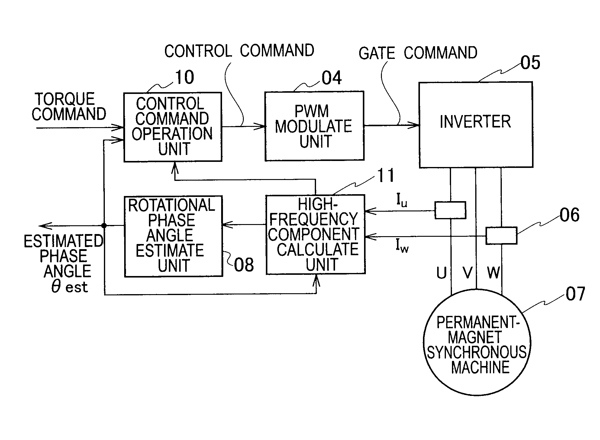
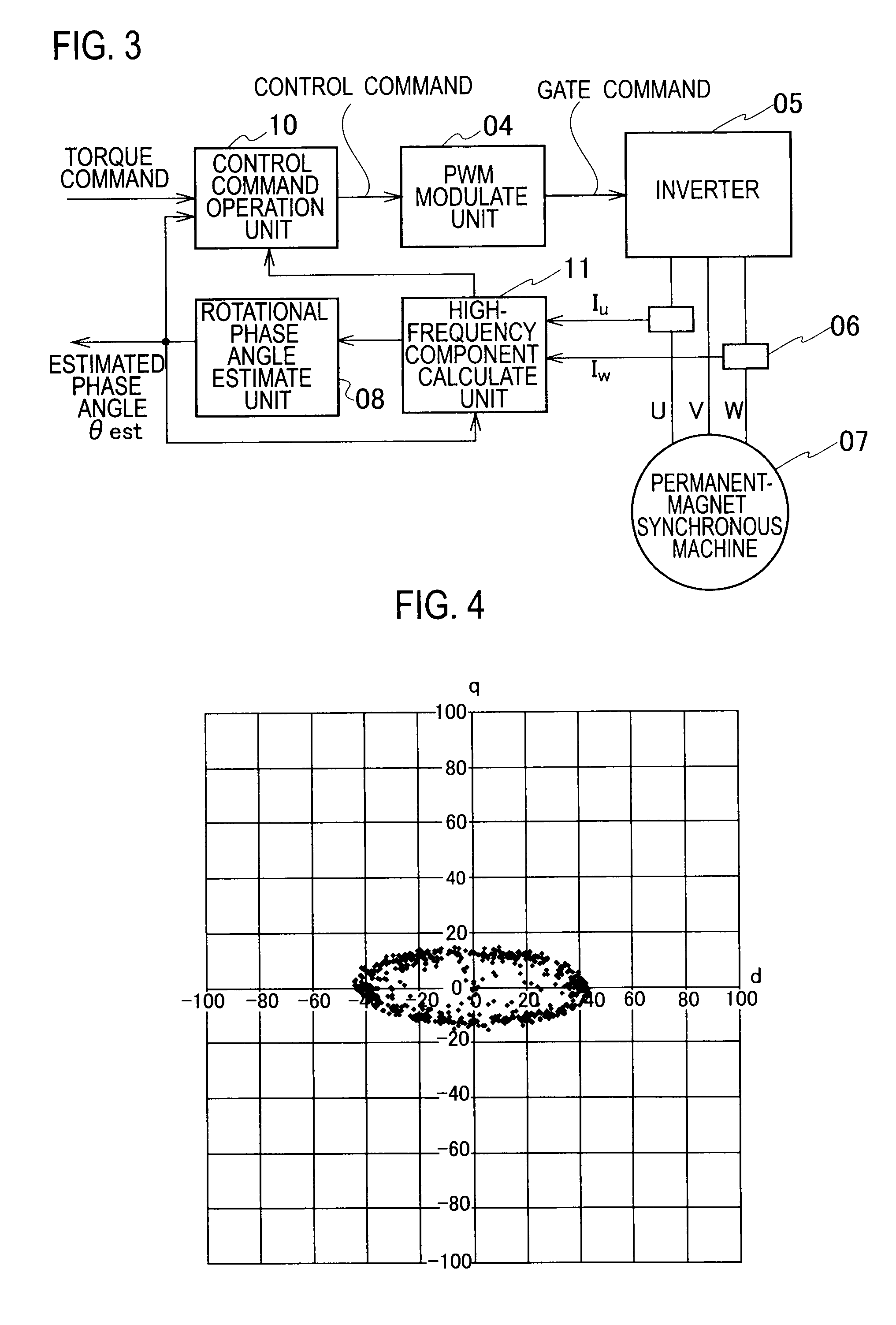
[0024]A sensorless control apparatus of a synchronous machine according to the present invention calculates high-frequency components of changes in currents passing through the permanent-magnet synchronous machine, estimates a phase angle of a motor rotor without a rotational phase angle sensor according to a spatial distribution of the high-frequency components on a dq-axes coordinate system synchronized with the rotation of the synchronous machine, and controls the permanent-magnet synchronous machine accordingly.

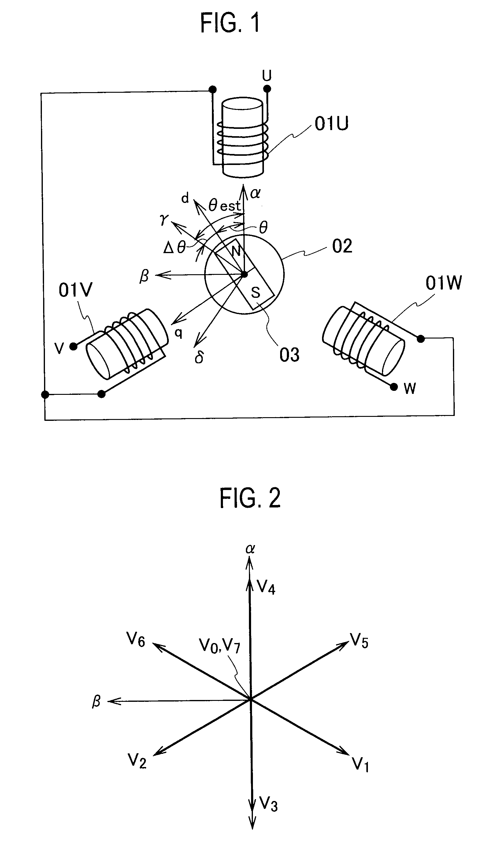
[0025]FIG. 1 shows a configuration of a standard permanent-magnet synchronous machine. A stator 01 of the permanent-magnet synchronous machine consists of three-phase windings 01U, 01V, and 01W and a rotor thereof consists of a rotor iron core 02 and a permanent magnet 03. In a sensorless control apparatus of a synchronous machine according to the embodiment, a coordinate system that turns in synchronization with the rotation of the permanent-magnet synchronous machine is...

second embodiment

[0057]A sensorless control apparatus of a synchronous machine according to a second embodiment of the present invention will be explained. The configuration of this embodiment is the same as that of the first embodiment shown in FIG. 3. This embodiment differs from the first embodiment in an operation carried out by the rotational phase angle estimate unit 08. This embodiment is characterized in that, in a high torque output state in which currents pass to saturate the inductance of the permanent-magnet synchronous machine 07, the embodiment estimates a rotational phase angle according to a change in the shape of a spatial distribution of high-frequency components of current changes.

[0058]Estimation of a rotational phase angle carried out by the rotational phase angle estimate unit 08 according to the first embodiment uses that a spatial distribution of high-frequency components of current changes indicates a rotor inductance of the permanent-magnet synchronous machine 07 and this h...

third embodiment

[0065]A sensorless control apparatus of a synchronous machine according to a third embodiment of the present invention will be explained. A configuration of the sensorless control apparatus of this embodiment is common to that of the first and second embodiments shown in FIG. 3. A rotational phase angle estimate process carried out by the rotational phase angle estimate unit 08 of this embodiment differs from those of the first and second embodiments. The third embodiment is characterized in that it calculates a feature value in a spatial distribution of high-frequency components of current changes on the dq-axes coordinate system, and according to the feature value, estimates a rotational phase angle.

[0066]This embodiment selects as a feature value a maximum value from among components detected in a predetermined angular orientation from the γ-axis in a high-frequency component distribution of current changes plotted on the γδ-axes. A relationship between the selected feature value...


PUM


Abstract

A sensorless control apparatus of a rotary machine includes an inverter 05 to invert DC power and AC power from one to another, a permanent-magnet synchronous machine 07 whose rotor has magnetic saliency and which receives power from the inverter and is driven thereby, a PWM modulate means 04 to determine an output voltage of the inverter according to a command for controlling the permanent-magnet synchronous machine, a current detect means 06 to detect a current passed to the permanent-magnet synchronous machine, a high-frequency component calculate means 10 to calculate high-frequency components of current changes caused by voltages that have been determined by the PWM modulate means and have been output from the inverter, and a rotational phase angle estimate means 08 to estimate a rotational phase angle of the permanent-magnet synchronous machine according to a spatial distribution of the high-frequency components on rotating coordinate axes synchronized with the rotation of the permanent-magnet synchronous machine. The apparatus is capable of suppressing an increase in loss and noise caused by the sensorless control of the rotary machine and stably operating with simple adjustments.

Description

TECHNICAL FIELD[0001]The present invention relates to a sensorless control apparatus of a synchronous machine.BACKGROUND ART[0002]Controlling and driving a synchronous machine (such as a motor and a generator) employing a permanent magnet as a rotor needs a sensor to detect a rotational phase angle of the rotor. A control apparatus that controls a synchronous machine with the use of the sensor to detect a rotational phase angle has the following problems.[0003]First, the presence of the sensor to detect a rotational phase angle increases the total volume of a drive system. This prevents the output of the synchronous machine from being intensified in a limited installation space.[0004]Second, the sensor to detect a rotational phase angle needs itself a maintenance checkup. This deteriorates the efficiency of an overall maintenance checkup.[0005]Third, a signal line from the sensor to detect a rotational phase angle may pick up noise and the like, and therefore, a detected value may i...

Claims


Application Information

Patent Timeline
Patent Type & Authority Applications(United States)
IPC IPC(8): H02P6/18H02P6/06H02P6/08H02P6/182H02P6/28H02P21/00H02P21/14H02P21/18H02P21/22H02P21/24H02P21/28H02P23/14H02P27/04H02P27/08
CPCH02P6/18H02P6/182H02P6/183H02P21/24
Inventor YASUI, KAZUYA
Owner KK TOSHIBA
Why Eureka
Try Eureka