
Thermocycling of a Block Comprising Multiple Sample

a technology of thermal cycle and multiple samples, applied in specific use of bioreactors/fermenters, biomass after-treatment, biochemical apparatus and processes, etc., can solve the problems of not allowing temperature control of heat sinks, not able to cool components at or below ambient temperature, and unable to cool objects below ambient temperature, etc., to achieve high thermal conductivity, maximize surface area, and low cost

Inactive Publication Date: 2009-08-13
ROCHE MOLECULAR SYST INC
View PDF16 Cites 20 Cited by
  • Summary
  • Abstract
  • Description
  • Claims
  • Application Information

AI Technical Summary

Benefits of technology

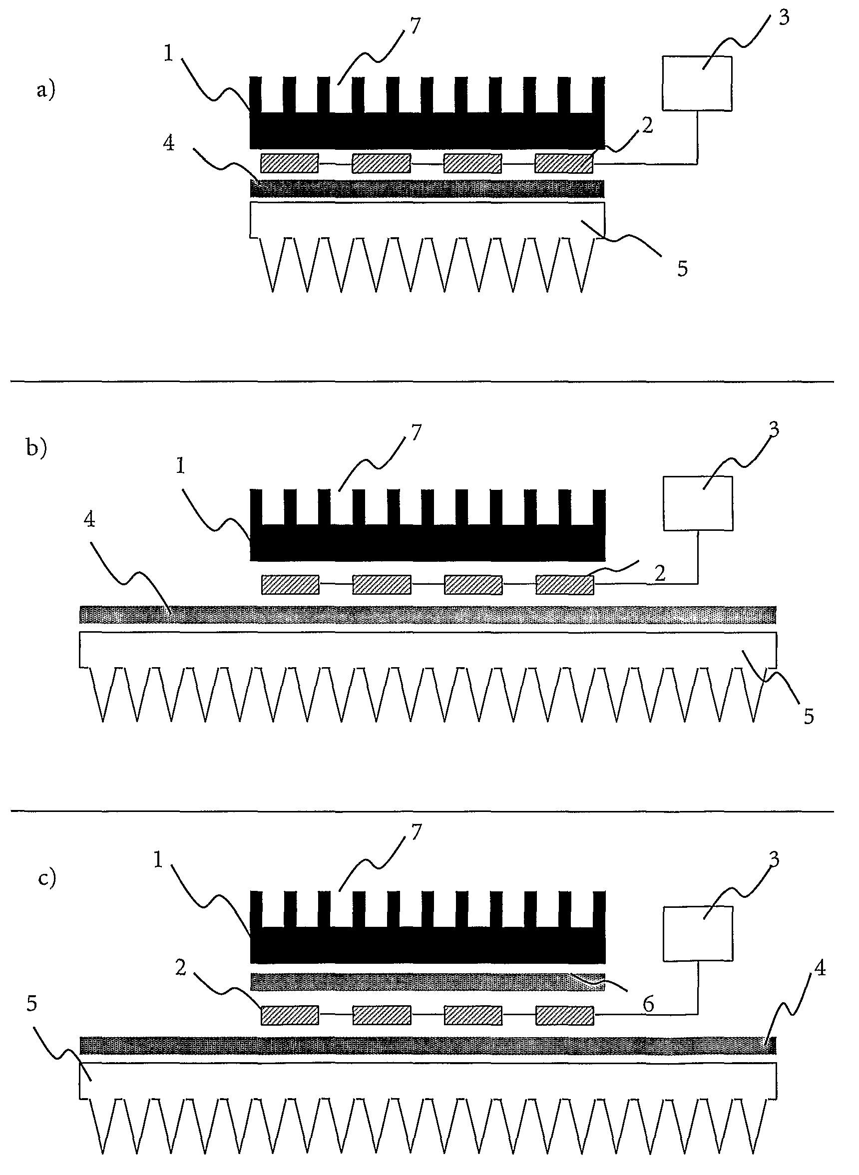
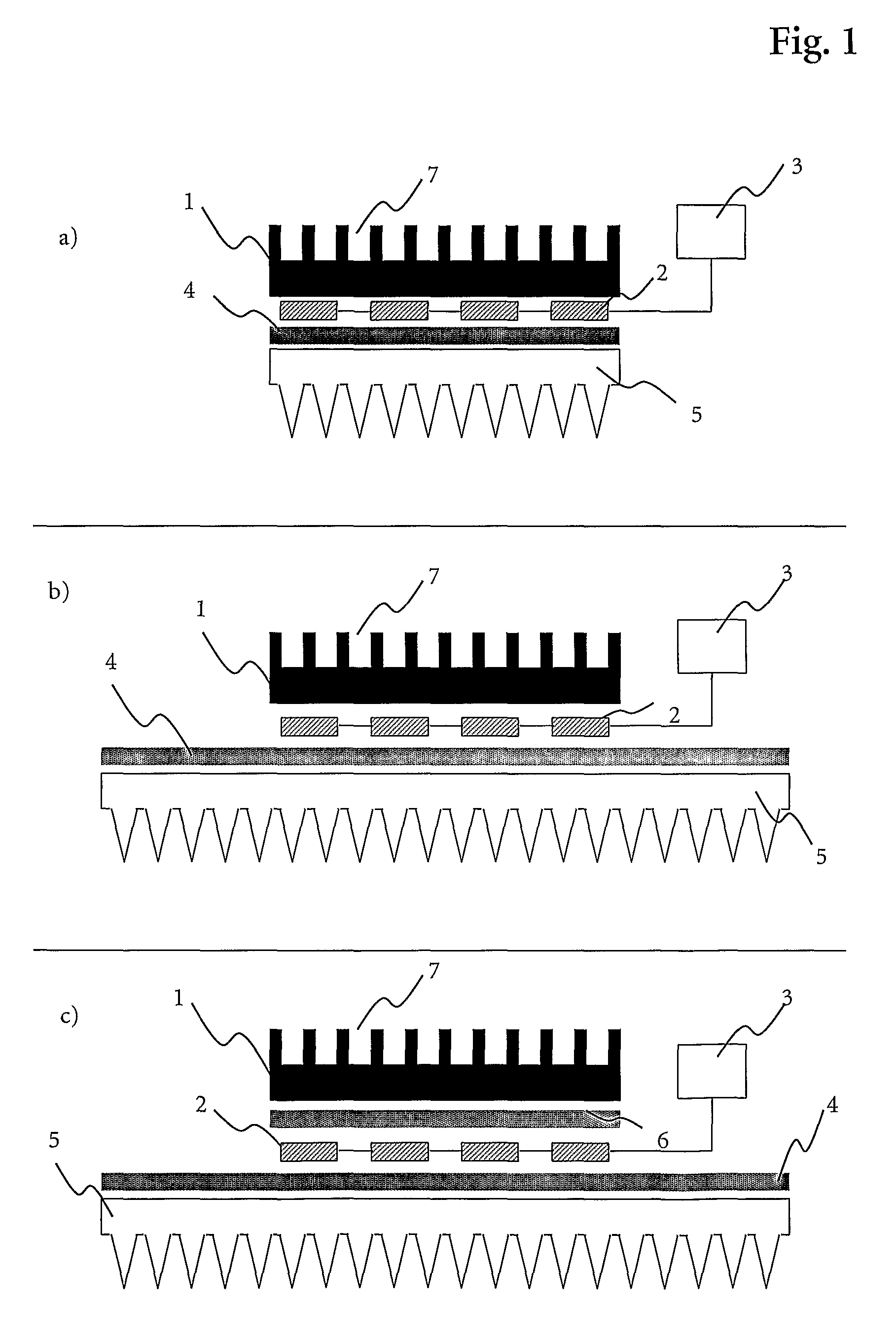
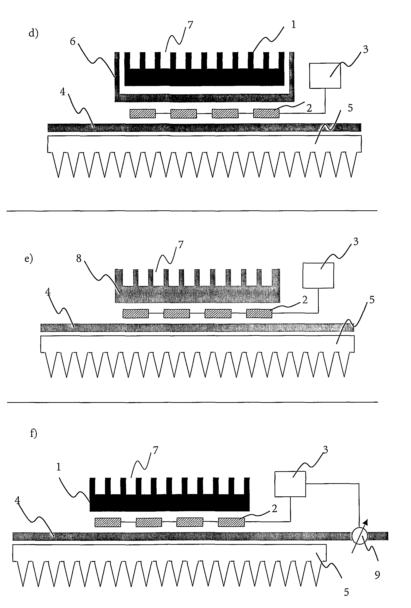
[0029]A heat sink 5 is a device to dissipate heat. In general, a heat sink is made out of a thermally conductive material analogous to the thermal block outlined before. Therefore, heat sinks are mostly made out of metal, preferably out of aluminum or copper. Another suitable material for heat sinks is graphite. Alternatively, heat sinks may be formed out of plastics and ceramics, if only a good thermal conductance is realized. In order to realize a maximum dissipation of heat, heat sinks are disposed to provide a large surface-to-volume ratio. This is realized by an assembly of fins arranged on a base plate. A large surface-to-volume ratio reduces the heat transfer resistance between the heat sink and the surrounding air.
[0121]The positive effect of a heat sink 5 as well as a first thermal base 4 that have both a larger cross section area as the thermal block 1 was discussed in detail before. In brief, using a first thermal base 4 in combination with a heat sink 5 improves the heat dissipation, because the enormous thermal conductance of the thermal base 4 assures that even a heat sink 5 being much larger than the heat source will participate effectively in the dissipative process.

Problems solved by technology

Heat sinks are inexpensive and offer installation flexibility but cannot cool components at or below ambient temperature.
Also, heat sinks do not permit temperature control.
Heat pipes are typically small and highly reliable, but they can not cool objects below ambient temperature.

Method used


Image

  • Thermocycling of a Block Comprising Multiple Sample
  • Thermocycling of a Block Comprising Multiple Sample
  • Thermocycling of a Block Comprising Multiple Sample

Examples


example 1

[0179]A device according to the present invention for the thermocycling of a 384 multiwell plate comprises a homemade thermal block out of the aluminum alloy AlMgSi 0.5. An aluminum block with the dimension 109×73×9.1 mm was used to form 384 recesses by drilling, each conic recess has a top diameter of 3.44 mm (angle 17°) and a depth of 6.8 mm.

[0180]Below said thermal block 6 Peltier elements are arranged, whereas the thermal contact is enhanced via a thermal conductive graphite foil. The used Peltier elements are suitable for multiple thermocycling procedures and can heat up to 130° C. Additionally, each of them has a cooling capacity of 75 W.

[0181]Via a second thermal conductive graphite foil, the 6 Peltier elements are arranged on a thermal base. The used thermal base is customized production of Thermacore™ and has the dimension of 248×198×5 mm. The vessel wall is made out of copper and the working fluid is water.

[0182]The used heat sink is commercially available from Webra (prod...

example 2

[0184]Heat pictures of the thermal block of a device as described in Example 1 were recorded with an IR-camera (commercially available at the company FLIR) during a heating procedure (FIG. 2) and a cooling procedure (FIG. 3).

[0185]The heating procedure (FIG. 2) started at a temperature of 55° C. with a heating rate of 4° C. / s until 95° C. were reached, whereas the cooling procedure (FIG. 3) started at a temperature of 95° C. with a cooling rate of 2° C. / s until 55° C. were reached. The pictures were taking at different times during the heating procedure and cooling procedure, respectively.

example 3

[0186]In FIG. 4 different characteristic temperatures of 6 successive temperature cycles of the following thermocycling protocol are plotted as a function of time:

steptempramphold timenumberPreCycle40° C.2.0° C. / s120 sec 1MainCycle95° C.4.4° C. / s10 sec655° C.2.0° C. / s10 sec72° C.4.4° C. / s10 sec

[0187]7 different temperature profiles are included in the figure, the temperature profile of the thermocycling protocol (‘Soll Temp’), the theoretical temperature of the thermal block (‘Soll Ist’), the measured temperature of the thermal block (‘Ist Temp’), the mean temperature measured within 9 recesses of the thermal block (‘Mean’), the minimal measured temperature of said 9 recesses of the thermal block (‘Min’), the maximal measured temperature of said 9 recesses of the thermal block (‘Max’) and the homogeneity of the 9 recess measurements (‘Hom’; homogeneity=maximal recess temperature—minimal recess temperature).

[0188]A standard multiwell plate was arranged in the recesses of the thermal ...


PUM


Abstract

The present invention relates to the field of high throughput analysis of samples. In particular, the present invention is directed to a device, a System and a method for simultaneous tempering of multiple samples. More particular, the invention relates to the simultaneous thermocycling of multiple samples to perform PCR in a microtiter plate format.

Description

FIELD OF INVENTION[0001]The present invention relates to the field of high throughput analysis of samples. In particular, the present invention is directed to a device, a system and a method for simultaneous tempering of multiple samples.PRIOR ART BACKGROUND[0002]Devices for tempering samples or reaction mixtures in a controlled way are used in almost all fields of chemistry or biochemistry, whereas basic science is affected in the same manner than industrial development or pharmaceutical production. Since labor time as well as reagents are expensive, development is tending to increase the throughput of production and analysis, while at the same time, to minimize the necessary reaction volumes.[0003]In general tempering devices have a thermal block that is in thermal contact with the sample under investigation. The thermal block is tempered to a desired temperature affecting the temperature of the sample, too. The simplest thermal block is a common boilerplate.[0004]In order to real...

Claims


Application Information

Patent Timeline
IPC IPC(8): C12P19/34C12M1/00
CPCB01L7/52B01L2300/0829B01L2300/1855B01L2300/06B01L2300/1822C12M1/38C12M1/00
Inventor SCHLAUBITZ, THOMASBURDACK, TORSTENFEDERER, PAULGEORGE, CHRISTIANGRUETER, GUIDOSCHOLLE, ANDREASTENZLER, GUENTER
Owner ROCHE MOLECULAR SYST INC
Learn More